® Operator's Manual Pedal Drive Lawn Tractor Models D609G G609G U609H X609G IMPORTANT: Read safety rules and instructions carefully before operating equipment. Warning: This unit is equipped with an internal combustion engine and should net be used on or near any unimproved forestcovered, brush-covered or grass-covered land unless the engine's exhaust system is equipped with a spark arrester meeting applicable local or state laws (if any).
TABLEOFCONTENTS Content Page Important Safe Operation Practices ................................................................... 3 Slope Gauge ...................................................................................................... 7 Tractor Set-up .................................................................................................... Know Your Lawn Tractor ...................................................................................
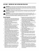
SECTION1: IMPORTANT SAFEOPERATION PRACTICES _ WARNING: This symbol points out important safety instructions which, if not followed, could endanger the personal safety and/or property of yourself and others. Read and follow all instructions in this manual before attempting to operate this machine. Failure to comply with these instructions may result in personal injury. When you see this symbol--heed its warning.
23. Mufflerandenginebecomehotandcancausea burn.Donottouch. 24. Checkoverhead clearances carefullybeforedriving underlowtreebranches,wires,dooropeningsetc., wheretheoperatormaybestruckorpulledfromthe unit,whichcouldresultinseriousinjury. 25. Disengage allattachment clutches,depressthe brakepedalcompletely andshiftintoneutralbefore attempting tostartengine. 26. Yourmachineisdesignedtocutnormalresidential grassofa heightnomorethan10".Donotattempt tomowthroughunusually tall,drygrass(e.g.
h. feature emphasises not to cut in reverse and to avoid back-over accidents; do not defeat it. g. Keep children away from hot or running engines. They can suffer burns from a hot muffler. allow space for fuel expansion. Replace gasoline cap andtighten securely. If gasoline is spilled, wipe it off the engine and equipment. Move unit to another area. Wait 5 minutes before starting the engine. k. To reduce fire hazards, keep machine free of grass, leaves, or other debris build-up.
10. Neverattempttomakeadjustments orrepairsto maximum safe operating speed of the engine. themachinewhiletheengineis running. 13. Maintain or replace safety and instruction labels, as 11.Grasscatchercomponents andthedischarge necessary. coveraresubjecttowearanddamagewhichcould 14. Observe proper disposal laws and regulations for exposemovingpartsorallowobjectstobethrown. gas, oil, etc. to protect the environment.
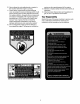
SIGHT AND HOLD THIS LEVEL WITH A VERTICAL TREE iq A POWER POLE A CORNER OFA BUILDING OR A FENCE POST W I,LI ..I &i Z n I.LI _IL WARNING Do not mow on inclines with a slope in excess of 15 degrees (a rise of approximately 2-1/2 feet every 10 feet). A riding mower could overturn and cause serious injury. If operating a walk-behind mower on such a slope, it is extremely difficult to maintain your footing and you could slip, resulting in serious injury.
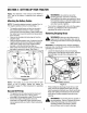
SECTION3: SETTINGUPYOURTRACTOR NOTE: Any reference in this manual to the RIGHT or LEFT side of the tractor is observed from operator's position. 4_b flammable and the vapors are explosive. Never fuel machine indoors or while the engine is hot or running. Extinguish cigarettes, cigars, pipes, and other sources of ignition. Attachingthe BatteryCables NOTE: The positive battery terminal is marked Pos. (+). The negative battery terminal is marked Neg. (-).
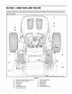
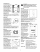
SECTION4: KNOWYOURLAWNTRACTOR Compare the illustration below with the controls on your tractor; get familiar with these features before you start to operate the tractor. This manual covers two models. So follow the descriptions and instructions pertaining to your tractor model only. F G H A K \ _ \ Figure A B C D E F G Systemslndicator Monitor/Hour Meter PTO (Power Take-off) Lever Choke Control Shift Lever Cup Holder Throttle Control Lever Parking Brake Button NOTE: Steering Wheel not shown for cl
Throttle ControlLever The throttle control lever is unattended. Always WARNING: Neverdisengage leave a running PTO, move machine shift lever into neutral position, set parking brake, stop engine and remove key to prevent unintended starting. / Choke* located on the right side of the tractor's dash panel. This lever controls the speed of the engine.
amperage. Refer to Battery charging procedure on page 21 or have the engine's charging system checked by an authorized dealer. Parking Brake Button To set the parking brake, fully depress the brake pedal and push the parking brake button in. Hold the Cup Holder button in while taking your foot off the brake pedal. Both the parking button and the brake pedal will then stay depressed. To release the parking brake, depress the brake pedal slightly.
SECTION5: OPERATING YOURLAWNTRACTOR _ WARNING: • • • • Read, understand, and follow all instructions and warnings on the machine and in this manual before operating. Insert the tractor key into the ignition switch. Place PTO lever in the disengaged (OFF) position. Engage the tractor's parking brake.
DrivingtheTractor Avoid turns when driving on a slope. If a turn must be made, turn down the slope. Turning up a slope greatly increases the chance of a roll-over. Avoid stopping when driving up a slope. If it is necessary to stop while driving up a slope, start up smoothly and carefully to reduce the possibility of flipping the tractor over backward. IMPORTANT: Avoid sudden starts, high speed and sudden stops.
• Keep the throttle lever in the FAST (rabbit) position for the most efficient use of the cutting deck or other (separately available) attachments. grass clippings repeatedly beneath the cutting deck. The ultra-fine clippings are then forced back into the lawn where they act as a natural fertilizer.
SECTION6: MAKINGADJUSTMENTS • _ WARNING: _ Disconnect the spark plug wire(s) and ground against the engine before performing any adjustments, repairs or maintenance. • WARNING: • DO not make any adjustments while the engine is running, except where specified in this or the engine manual. If the cutting deck appears to be mowing unevenly, a side to side adjustment can be performed.
SeatAdjustment SteeringAdjustment ,_ If the tractor turns tighter in one direction than the other, or ifthe ball joints are being replaced due to damage or wear, the steering drag links may need to be adjusted. WARNING: Before operating this machine, make sure the seat is engaged in the seat stop, stand behind the machine and pull back on seat until fully engaged into stop.
SECTION7: MAINTAININGYOURLAWNTRACTOR Oil RII Cap any _ WARNING: maintenance orBefore repairs,performing disengage PTO, move shift lever into neutral position, set parking brake, stop engine and remove key to prevent unintended starting. Oil Drain Hose \ \ Protective Cap CleaningEngineandDeck • • Promptly wipe off any fuel or oil spilled on the machine.
SECTION8: SERVICE any _lb WARNING: maintenance orBefore repairs,performing disengage PTO, move • shift lever into neutral position, set parking brake, stop engine and remove key to prevent unintended starting. • CuttingBlades • ,_ • Test the blade by balancing it on a round shaft screwdriver. Grind metal from the heavy side until it balances evenly. IMPORTANT: A poorly balanced blade will cause excessive vibration and may cause damage to the tractor and/or personal injury.
substitute (non-OEM) V-belt can be dangerous by not disengaging completely. For a proper working machine, use factory approved belts only. All belts on your tractor are subject to wear and should be replaced if any signs of cracking, shredding or rotting are present. To change or replace the deck belts on your tractor, proceed as follows: • • • • Figure 11 • • • • Move the deck lift lever into the top notch on the right fender to raise the deck lift arms up and out of the way.
IMPORTANT:The V-belts found on your tractor are specially designed to engage and disengage safely. A substitute (non-OEM) V-belt can be dangerous by not disengaging completely. For a proper working machine, use factory approved belts. • NOTE: Slowly rotate the pulley counter-clockwise the belt off it. • To change or replace the drive belt on your tractor, proceed as follows: NOTE: It is recommended Remove the upper drive belt from around the transmission pulley and the variable-speed pulley.
• • • • • • Slide belt off the variable-speed pulley as you lift the pulley up and out through battery tray opening. Remove the rear idler pulley from the double- idler bracket while unrouting the belt from around both the rear and the front idler pulley. See Figure 13. Remove the hex bolt from the center of the engine pulley and gently lower it off of the engine crankshaft. Be careful not to lose any washers or spacers which may be on top of the engine pulley.
WARNING: Batteries give off an explosive gas while charging. Charge battery in a well ventilated area and keep away from an open flame or pilot light as on a water heater, space heater, furnace, clothes dryer or other gas appliances. • " If the electrical system does not function, or your tractor's engine will not crank, first check to be certain that the fuse has not blown. It can be found under the hood mounted behind the top of the dash panel on the support bar.
SECTION10: TROUBLESHOOTING Trouble Possible Engine fails to start PTO lever engaged. Parking brake not engaged. Spark plug wire(s) disconnected. Throttle control lever not in correct starting position. Choke not activated Engine runs erratic Corrective Cause(s) Fuel tank empty, or stale fuel. Blocked fuel line. Faulty spark plug. Engine flooded. Unit running with CHOKE applied. Spark plug wire loose. Blocked fuel line or stale fuel. Vent in gas cap plugged. Water or dirt in fuel system.
SECTION11: PARTSLISTFORMODELSD609,G609,U609 & X609 < 30 28.
ModelsD609,G609,U609 & X609 REF. NO. PART NO. DESCRIPTION REF. NO. 1 783-1346 Grill Support Bracket (9-style) 2 710-0599 3 710-0528 Self-tapping Screw, 1/4-20 x .5 Hex Cap Screw, 5/16-18 x 1.25 4 710-0924 Phillips Pan Screw, 1/4-20 x .75 5 710-1017 Truss Phillips Screw, 1/4-20 x .625 26 27 PART NO. DESCRIPTION 751-0659A Fuel Tank, Two-gallon (Model D609G) 725-1745 Ignition Key w/plastic 725-1744 Ignition Key w/o plastic cover 710-0895 Self-tapping cover Screw, 1/4-15 x .
ModelsD609,G609,U609 & X609 49 48.
ModelsD609,G609,U609 & X609 REE NO. 1 2 3 4 5 6 7 8 9 10 11 12 13 14 15 16 17 18 19 20 21 22 23 24 25 26 27 28 PART NO. 747-1130A 683-0197 711-0332 712-0206 712-0431 712-3004A 712-3083 714-0104 714-0145 716-0106 720-0311 732-0874 732-1184 736-0275 736-0921 736-3019 736-3084 738-0138A 738-0143 741-0225 741-0715 746-0968 747-1111 756-1154 783-0678A 783-0720A 710-0260A 710-0604A DESCRIPTION Deck Stabilizer Rod Lift Shaft Assembly Clevis Pin, .5 x .
ModelsD609,G609,U609 & X609 43 42 24 46 f 23 19 6 21 38 20 41 B .
ModelsD609,G609,U609 & X609 REF. NO. 1 2 3 4 5 6 7 8 9 10 11 12 13 14 15 16 17 18 19 20 21 22 23 24 PART NO. 731-1291A 710-1238 783-0726B 783-0727A 783-0728 710-0723 711-1408 711-1655 712-0240 712-0241 712-0431 712-0459 712-3004A 717-1550D 717-1554 723-0448A 736-0169 736-3084 738-1001A 741-0475 741-0656 738-0372B 731-2624 731-2625 DESCRIPTION REE NO. 25 26 27 28 29 30 31 33 34 35 36 Pivot Bar End Cap Self4apping Screw, 16-18 x .
ModelsD609,G609,U609 & X609 5\ •73 _-23 B I 8_\ A \ 81\ 51 J J 80 15 f 39j _16 30
ModelsD609,G609,U609 & X609 REE NO. 1 2 3 4 5 6 7 8 9 10 11 12 13 14 15 16 17 18 19 20 21 22 23 24 25 26 27 28 29 30 31 PART NO.
ModelsD609,G609,U609 & X609 REE NO. 1 2 3 4 5 6 7 8 9 10 11 12a 12b 12c 13 14 15 16 17 18 19 20 21 22 23 24 25 26 27 28 29 30 9 PART NO. 716-0231 721-0338 711-1431 741-0340 736-0495 717-1362 717-1363 750-1234 718-0228 741-0525 719-0394 736-0336 736-0337 736-0349 736-0519 741-0336 741-0337 750-1238 611-0133 618-0424 661-0006 710-1325 710-1206 717-0678 732-0863 741-0862 761-0202 711-1430 716-0108 717-1464 719-0391A 736-0723 DESCRIPTION E-Ring, .75 Seal, .75 x 1.0 x .125 Drive Shaft Sleeve Bearing, .75 x .
ModelsD609,G609,U609 & X609 I (for choke) _13 4 24 NOTE: REF. NO. 1 2 3 4 5 6 7 8 9 10 11 12 13 14 15 27 31 Engine accessory parts are applicable to all models except otherwise noted. PART NO. 710-0227 710-0599 710-0604A 710-1237 710-1314A 710-1315 712-3017 721-0460 726-0205 736-0119 736-0300 751 B221535 751-0535 751-0564 751-0616 REP. NO. DESCRIPTION Self-tapping Screw, #8-18 x .5 Self-tapping Screw, 1/4-20 x .5 Self-tapping Screw, 5/16-18 x .625 16 17 18 Screw, #10-32 x .
ModelsD609,G609,U609 & X609 33 34_ _38 16.
ModelsD609,G609,U609 & X609 REE NO. 1 2 3 4 5 6 7 8 9 10 11 12 13 14 15 16 17 18 19 20 21 22 23 24 25 26 27 28 29 PART NO. 647-0064 683-0450 710-0276 710-0520 710-0831 710-1238 712-0229 712-0431 712-3004A 712-3010 714-0470 726-0201 731-2111A 732-1170 732-0991A 736-0108 736-0119 736-0140 736-0275 736-3000 736-0331 736-3039 738-0372B 741-0708 747-1112D 747-1286A 748-0415B 756-0627B 756-1208 DESCRIPTION PTO Engage Lever Assembly PTO Engage Plate Assembly Carriage Screw, 5/16-18 x 1.
ModelsD609G,G609G& X609G 8 24 36 45 1235 20 29 9 50 11 21 e 34 18 28 32 31 38 40 40 37 17 51 53 36
ModelsD609G,G609G& X609G REF. NO. PART NO. DESCRIPTION REF. NO. PARTNO. DESCRIPTION 1. 16606 Bracket: Retainer Hook 28. 732-O3O6 Compression Spring 2. 618-0565 Spindle Assembly: Pulley 29. 732-0470A Extension Spring 3. 683-0198E Deck Assembly 30. 732-1165 Extension Spring 4. 683-0254 Deck Hanger Bracket LH 31. 734-0973 Deck Wheel 5. 683-0440 Brake Assembly: deck 32. 736-0105 Bell Washer 6. 710-0520 Hex Screw 3/8-16 x 1.5 33. 736-0119 Lock Washer 7.
ModelU609H 50\ 11 \\ 57 29 3 14 34 5 26 38 38 39 25 2 • 9 45 26 37 20 1_ 4 16 16 62 60_ _ 59 55 _g 9 15 18 g 19 24 24 38
ModelU609H REF. NO. PART NO. DESCRIPTION REF. NO. PART NO. DESCRIPTION 1. 16606 Retainer hook: bracket 32. 726-0233 Push Nut 2. 17116 Deck Brake Assembly 33. 732-0306 Compression Spring 3. 17258C Belt Cover RH 34. 732-0429A Extension Spring 4. 17982 Spindle Plate 35. 732-594A Extension Spring 5. 618-0240A Spindle Assembly 36. 732-0934 Extension Spring 6. 618-0594 Spindle Assembly: Double Pulley 37. 732-1165 Extension Spring 7. 683-0254 Deck Hanger Bracket LH 38.
MANUFACTURER'S LIMITED WARRANTY The limited warranty set fodh below is given by Troy-Bilt LLC with respect to new merchandise purchased and used in the United States, its possessions and territories. d. Troy-Bilt LLC warrants this product against defects for a period of two (2) years commencing on the date of original purchase and will, at its option, repair or replace, free of charge, any part found to be defective in materials or workmanship.