
Manual

Section2: Assembly
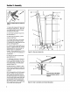
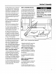
9. Whenshift arm (X)is in neutralposi-
tion, rotateshift link (P)toward endof
gearselectleverrod (I). Adjustlength
of shift link (P) as necessaryto fit into
hole in bottom of gearselectlever (I).
NOTE:Pin (K) on GearSelectLever(I)
must beheld inthe neutralposition
detentonthe shift quadrant(see Figure
2-6) while shift link (P, Figure2-7) is
adjusted.
10. Inserthookedendof shift link (P,
Figure2-7) into holein bottom end of
gearselectlever(I) andsecurewith
hairpinclip (Q).
NOTE:It may benecessaryto lift gear
selectlever (I) to install shift link (P).
11. Removeunitfrom shipping crate.
To remove,hold down Operator
PresenceControllever(W, Figure2-5)
which releasesthe wheel brake.
12. With unit on levelground,hold
down OperatorPresenceControllever
(W, Figure2-5) and push unit forward
and backward.Thewheelsshouldmove
freely. If not, adjust length ofshift link
(P, Figure2-7) as necessary.
13. Putthe GearSelectLeverin neutral
(N), releaseall of the control leversand
try to push the unit forward and back-
ward. The wheelsshould not turn. If
they doturn, an adjustmentis neces-
sary. DONOTOPERATETHEUNIT
UNTILTHEWHEELBRAKEMECHANISM
HASBEENADJUSTEDAND ISWORK-
INGPROPERLY.See"WheelBrake
Adjustment"in Section5 "Maintenance."
STEP5: Secure Wire Harness
1. At the unattachedendof the electrical
wire harness,therearefour wires at-
tachedto a largeplasticconnectorand
two wires attachedto a small plastic
connector.. Plugthe largeconnector
into the bottom of the ignitionkeyswitch
that is locatedon the undersideof the
handlebarconsole(not pictured).
3. Usetwo cableties to securethe wire
STEP6: Check Motor Oil Level
1. Movemowerto a levelarea.Press
and hold OperatorPresenceControl
lever (W,Figure2-5) to movemower.
2. Themoweris shippedwith oil in the
engine. However,you MUSTcheckthe
oil levelaccordingto the instructionspro-
vided intheseparateEngineOwner's
Manualincludedinthe unit'sliterature
packagebeforestartingthe mower.
Do not use the mower if the wheels
continue to turn after releasing the
Operator Presence Control and the
WheelDriveControl.
Severe personal injury or property
damagecouldresult if this instruction
isnotfollowed.
I f o
Figure2-7: Detail- TransmissionNeutralAdjustment.
• Keepoil levelat the FULLmarkon the
dipstick to avoidenginedamage.
• Changeoil accordingtoscheduleand
instructionsin Section5 "Maintenance."
STEP7: Check Tire Pressure
1. Useatire gaugeto checkthe air
pressurein the reartires. Theair pres-
sure should bebetween15-20 PSI (20
PSI maximum).
2. Keepboth tires equallyinflatedto
helppreventmachinefrom pullingto
oneside.
STEP8: After Assemblingand
Before UsingUnit
1. Readthis entire Owner'sManualfor
harnessto the right handlebarandaway o.
from any movingparts. Placethe ties propersaTety,operationand mainte-
anequaldistanceapart, nanceinformation.
2. Makesure sparkplug wire is con-
nectedto sparkplug beforestarting unit.