
Manual

Section2: Assembly
BB
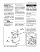
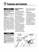
Figure2-4A:Attachwheeldrivecontrolrod
to lever.
1. Removethevinyl grip (B, Figure2-6)
from the gearselect lever (I). Placethe
wood edgeagainstthe edgeof the grip
andslowly pull off thegrip.
2. Insertnylon bushing(Z, Figure2-6)
up into console(L).
3. Slidespring andwashers (J) down
onto gearselectlever.
4. Insertgearselectlever(I) upthrough
nylon bushing(Z) in handlebarconsole
(L). Guidepin (K)ongearselectleverinto
grooveinshift quadrant(P).
5. Holdlowerpartof gearselect lever(I,
Figure2-7) againstbracket(M). Position
retaining plate(N), removedearlier, as
shown in Figure2-7 (plate below
bracket). Secureplatewith two 1/4"-20x
1/2"screws(0) and1/4"-20 Iocknutsre-
movedearlier.
6. Slidegrip (B, Figure2-6) backonto
gearselectlever(I).
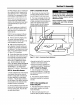
7. Rotategearselectlever(I, Figures2-
6 & 2-7) clockwise until spur (K - short
rod) ongearselect rod stops in the neu-
tral position detenton the shift pattern
quadrant(Figure2-6).
8. Moveshift arm (X, Figure2-7) from
side to sideas necessaryinto eachtrans-
mission geardetentuntil transmissionis
in neutral.
NOTE:Movingshift arm (X) allthewayto
the left, andthen onenotch backto the
right, should put transmissioninto neu-
tral. Whentransmission is in neutral,unit
will movefreely whenpushedwhile hold-
ingthe OperatorPresenceControllever
(W, Figure2-5) down.If transmissionis
NOTin neutral,therewill beaslight drag
on the wheelswhen pushingunit.
W
J
V
F
G N
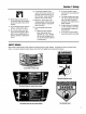
Figure2-5: Rearviewofcontrolrods.
0
M
C
f
2
K
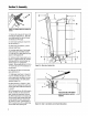
Pin(K)mustbeinthisdetent
whentransmissionneutralis --_
adjusted.
Figure2-6: Detail- GearSelectLeverin Neutral(N) position.
6