
Manual

Section2: Assembly
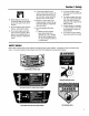
STEP3 ATTACHINGTHEBATTERY
CABLES(MODEL F753B)
Thepositive batteryterminal is marked
Pos.(+). The negativebatteryterminal is
markedNeg.(-).
The mowerisshippedwith the positive
(Red) cablesecuredto the positiveter-
minal (+) onthe battery.Attachthe
ground (Black)cableto the negativeter-
minal (-) onthe battery,asfollows:
1. Removethe plasticbatterycover (G,
Figure.2-3) by unthreadingthe two wing
nuts (H, Figure. 2-3) which secure it to
the batteryhold-down rods (I, Figure.2-
3)
2. Remove the hex bolt and hex nut
from the groundcable/ heavyblackwire
(E, Figure.2-3).
3. Securetheground cableto thenega-
tive batteryterminal (-) with the boltand
hex nut just removed.
IMPORTANT:
• If the batteryis put into serviceafter
the dateshown ontop of battery,
chargethe batteryas instructedin the
Maintenencesectionof this manual
prior to operatingthe tiller.
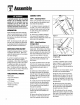
STEP4: Attach Control Rods
A. AttachWheel DriveControlRod
1. Locatethewheel drivecontrol rod (F,
Figures2-4A & 2-7) and removethe an-
gledendfrom the left handlebarby re-
movingthe hairpinclip whichsecuresit
to the Wheel DriveControllever (V,
Figure2-4A)
2. Atleft sideof enginedeck, insert
swivel block (H,Figures2-4 & 2-5) on
wheeldrive control rod into wheeldrive
control arm (U, Figure2-4).
3. Adda5/16"washer(A, Figure2-4)
andsecurewith a hairpinclip (B).
4. Atupperend of control rod, re-insert
the angledend into theWheelDrive
Controllever(V,Figure2-4A) and re-
attach with hairpinclip (BB) removed
earlier.
B.AttachOperatorPresenceControl
Rod
1. LocatetheOperatorPresenceControl
rod (E, Figures.2-4 and 2-5). At bottom
of control rod, insert swivel block (G,
Figures2-4 & 2-5) into control arm (T,
Figure2-4).
H
Black
(NegativeCable)
H
Red /
(PositiveCable)
Figure2-3: Connectwireterminalsto batteryterminals.
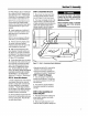
Controlrodsare adjusted at the fac-
tory andshouldnot requireadditional
adjustmentduringassembly.Afteras-
sembling unit, control rod
adjustment should be checked (and
re-adjusted,ifnecessary)accordingto
informationin MaintenanceSection.
Failureto follow this instructioncould
result in severe personal injury or
propertydamage.
2. Add one5/16"washerand secure
with hairpinclip.
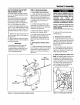
C.AttachBladeDriveControlRod
1. Locatethe bladedrive control rod (C,
Figure2-5). Insert oneendof control rod
into bladedrive bracket (D,Figure2-5).
Add one5/16"washerandattachwith
hairpinclip (CC).
2. Insertthe other endof rod into bot-
tom endof BladeDriveControl lever(J,
Figure2-5). Add one5/16" washerand
attach with hairpin clip (AA).
D. AttachandAdjustGearSelectLever
NOTE:The retainingplate (N,Figure2-5)
mentionedin the following steps is se-
cured to the rearof the mowerwith two
screws (O, Figure2-5) and1/4"-20 lock-
nuts. Removethe retainingplateand
saveit, along with thetwo screws,be-
fore proceedingwith assembly.
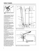
W
H A,B _G
Figure2-4:Left-handcontrolrodsdetail.