
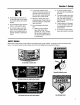
Manual
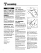

Assembly
ASSEMBLYSTEPS
To preventpersonalinjuryor property
damage, do not attempt to start the
engine until all assembly steps are
complete and you have read and
understand the safety, controls and
operatinginstructionsinthismanual.
INTRODUCTION
Pleasecarefullyfollow theseassembly
steps to properly prepareyour machine
for use. We recommendthat you read
this Sectionin its entirety beforebegin-
ningassembly.
STEP1: Unpacking Mower
NOTE:LEFTand RIGHTsides of the unit
areasviewedfrom the operator'sposi-
tion behindthe handlebars.
1. Cutstraps, if present,securingunit
to pallet. Leaveunit on pallet during as-
sembly (to safelyremoveunitfrom pal-
let, wait until you havecompletedas-
sembly steps 1-4).
2. Removeanyprotectivepackaging
from aroundthe handlebars.Cutthe
plastic tie straps holdingthe control rods
and struts to the handlebars.
NOTE:All referencesto left, right,front
and rearof the machineare determined
by standingbehindthe handlebarsand
facingthe direction offorward travel.
INSPECTIONAFTERDELIVERY
Inspectthe shipping crateand machine
immediatelyafterdelivery. Makesure
neitherthe carton/cratenor the contents
havebeendamaged.
If you find or suspectany damage,con-
tact the carrier (trucking company)
immediately. Inform them of the specific
damageandthatyou wish to file a claim.
To protectyour rights, besureto put
this in writing to the carrier within 15
days. Thecarrier will let you knowhow
to proceedwith your claim. Pleaselet us
knowif you needanyassistance.
STEP2: Attach Handlebars
to Engine Deck
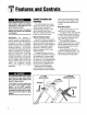
NOTE:Fourscrews(D, Figure2-2) are
usedto connect the handlebarsto the
enginedeck. At thefactory, two of these
screws (front) arethreadeddirectlyinto
lock nuts weldedto the backsidesof the
deck.The remainingtwo screws (rear)
securethe lower handleto the deck.
1. Removeandsavethe two 5/16"-18x
3/4"screws (front) mentionedin the
NOTEabove.
2. Loosen,but do NOTremove,the two
5/16"-18x 3/4" screws(rear). Leavethe
cardboardinsertfound betweenthe left-
hand handlebarandenginedeck,in
place.
3. Carefullypivot the handlebarsover
• Wire Cutter
• Two7/16" Wrenches
• 3/8" Wrench
• 1/2" Wrench
• Scissorsor PenKnife
the engineandpositionthe handlebar
TOOLS/MATERIALSNEEDED: ends (E, Figure2-2) againstthe sides of
the enginedeck. Do not alloow the han-
dlebarsto rubagainsttheenginewhile
pivoting them.
4. Looselysecurethe right-hand handle-
barendto the deck by reinsertingthe
screw (D, Figure2-2) removedearlier.
• Needle-nosePliers
Donot securethe left-handhandleat
• Tire Gauge this point in assembly.
5. Removethe cardboardinsertfrom
betweenthe left-handhandlebarand
enginedeck
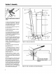
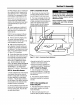
8. Removethe nut from the lower screw
(B, Figure2-1) which securesthe con-
sole to the handlebaron theleft-hand
Figure2-1
D D ,
i
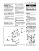
Figure2-2: Attachhandlebarsandstruts
toenginedeck.
side of the unit.
7. Positiona handlebarstrut's smaller
hole (A, Figure2-1) over the screw (B,
Figure 2-1) on the INSIDEof the con-
sole,with the strut's flat side againstthe
console.
8. Usingthe nut removedearlier,secure
the strut to the console/handlebar.
9. Align the loose endof the left-hand
handlebarstrut (A, Figure2-2) over the
front holein the handlebarend. Secure
the strut and handlebarto thedeckwith
the 5/16"-18x 3/4" screw(D, Figure2-2)
removedearlier.
10. Removethe screw (front) that is
looselysecuringthe right-handhandle-
barendto the deck.and repeat6-9 on
the right-handside of the unit.
11. On both sidesof the unit, securely
tightenthe screws(D, Figure2-2) at the
lower ends of the handlebarbeforetight-
eningthescrews (B & F,Figure2-1) on
the console.