
Manual


Section5: Maintenance
W!_LY_II:I;t_II_[_I Beforeinspecting,cleaningorservicingthemachine,shutoffengine,waitformovingpartsto stop,disconnectspark
i_ _ plugwireandmovewireawayfromsparkplug.Removeignitionkey(electricstartmodels).
Failuretofollowtheseinslxuctionscanresultinseriouspersonalinjuryorpropertydamage.
BLADEBRAKEREPLACEMENT
Followthis procedureto installa new
bladebrake.
To RemoveBladeBrake:
1. Stopengine,wait forall partsto
stopmoving,anddisconnectspark
plugwire.
2. Removebelt coveras describedin
"Belt CoverRemoval"instructions.
3. Removehardware(G, Figure5-8)
securingbladebrake(H).
4. Removeold brake(H) from idler
arm (I).
To Install Brake:
1. Positionnew brake(H) in placeon
idler arm (I).
2. Centerbrakein sheavegroove and
securebrake(H)with hardware(G) re-
movedearlier.
3. Reinstallbeltcover securely.
4. Test operationof bladebrake(see
"BladeBrakeControlTest" in Operation
section).
BLADEDRIVEBELT
ADJUSTMENT
Ifthe bladedrive belt is slipping dueto
lackof belttension,follow the steps
below.
1. Stopengine,wait forall partsto
stopmoving,anddisconnectspark
plugwire.
2. Removebelt coveras describedin
"Belt CoverRemoval"instructions.
3. With moweron levelground,adjust
bladecuttingheightat about 3" (mea-
sure from ground to flat portion of
blade).
4. With the BladeDriveControl (Figure
5-7) inthe disengagedposition, set a
gapof 1/8"betweenthe spring (F,Figure
5-9) andflat washer(E)byadjustingthe
nut (g).
5. Reinstallthe belt coversecurely.
20
\
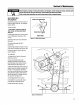
Adjust idlerin direction
of arrow to tighten blade
...drive belt
D
1/8" E
Figure5-9:Bladedriveadjustment.
6. Testthe operationof the bladebrake
(see"BladeBrakeControlTest" in the
Operationsection).
7. If the drive beltslips during opera-
tion, it may benecessaryto
relocateidler (J, Figure5-9) in the slot
providedin the mounting bracket.With
theenginestoppedandthesparkplug
wiredisconnected,loosenthehardware
onthe idler(J)and slide it forward to
take upslackinthe belt.
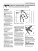
8. Engagethe bladedrive and measure
the distance(X, Figure5-8) betweenthe
centers of pulleys(K) and(L). Thedis-
tanceshould be5-1/2 to 5-5/8". After
obtainingthe correct dimension,rein-
stall the belt coversecurelyandtest the
operationof the bladebrake.
BLADEDRIVE CONTROLLEVER
ADJUSTMENT
Makethe following adjustmentif the
BladeDriveControlLever releasesdur-
ing operation.
1. Stopengine, waitforall partsto
stopmoving,anddisconnectspark
plug wire.
2. Engagethe OperatorPresence
Controlandthe BladeDriveControl.
Without releasingthe controls, look in-
side the cutout atthe rearof the frame
and makesure the OperatorPresence
Controllatches(Aand B, Fig.5-10) are
fully engagedat point (C). If theyare not
fully engaged,improper operationor
prematurewearcould result. To adjust,
loosen hexnut (D) andshortenlengthof
control rod (E).To avoid over-adjusting,
turn rod only 1 to 2 turns per adjust-
ment.
3. Tighten hexnut securelyafter adjust-
ing control rod.
4. Test by releasingthe Operator
PresenceControl. If properlyadjusted,
the BladeDriveControlwill disengage
when the OperatorPresenceControlis
released.Re-adjustas necessaryby
repeatingSteps2 and3.
C
E A
Figure5-10: BladeDriveControlLever
adjustment.