
Manual


AttachingSideDischargeChute
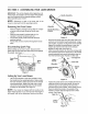
This mower can side discharge grass clippings. Follow
instructions below to ready this mower for side
discharge operation.
Remove mulching baffle from unit by disconnecting
wing nuts.
Attach side discharge chute to unit and secure with
the three wing nuts. See Figure 7.
Side Discharge
Chute
Figure 7
SECTION6: MAKINGADJUSTMENTS
WARNING: Do not at any time make any
adjustment to lawn mower without first
stopping engine and disconnect spark plug
wire.
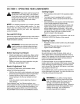
HandleHeightAdjustment
Your mower is shipped with the handle in the higher
height position. To lower the handle height, proceed as
follows.
Remove the starter rope from the rope guide.
Remove the upper handle by removing the hand
knobs and carriage bolts. Lay the upper handle out
of the way, being careful not to bend or kink the
cables.
Remove the hairpin clips from the weld pins on the
handle brackets. Press out the legs of the lower
handle. Remove the lower handle from the mower.
Turn the lower handle around so the notch on the
bottom of the lower handle is facing forward as
shown in Figure 8.
Reassemble, placing the bottom holes in the
handle over the weld pins in the handle mounting
bracket.
Place the hairpin clips in the inner holes in the weld
pins and insert the carriage bolts in the upper hole
on the handle mounting bracket and secure with
plastic wing nuts.
Reassemble the upper handle to the lower handle.
Attach the starter rope as instructed in the
assembly section.
Lower Handle
Notch
Figure 8
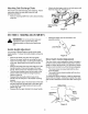
Drive ClutchControlAdjustment
The drive clutch control adjustment wheel is located in
the drive clutch control handle housing and is used to
tighten or loosen the drive belt. You will have to adjust
the drive clutch control if any of the following happens:
The mower does not propel itself with the drive
clutch engaged.
The mower's drive wheels hesitate with the drive
clutch engaged.
To resolve the above problems, rotate the adjustment
wheel with your fingers. Clockwise to tighten the cable
and counter-clockwise to loosen the cable. See Figure
9.
BottomView
® ®
Adjustment Handle
Wheel_
Drive Clutch
Control
Figure 9
10