Operator’s Manual Easy Star TM M 2-Cycle Gasoline Trimmers Model TB75SS or TB25CS IMPORTANT: READ SAFETY RULES AND INSTRUCTIONS CAREFULLY P/N 769-02211 (1/06)
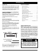
INTRODUCTION THANK YOU TABLE OF CONTENTS Thank you for buying this quality product. This modern outdoor power tool will provide many hours of useful service. You will find it to be a great labor-saving device. This operator’s manual provides you with easy-tounderstand operating instructions. Read the whole manual and follow all the instructions to keep your new outdoor power tool in top operating condition. Service Information . . . . . . . . . . . . . . . . . . . . . . . . .2 Rules for Safe Operation .
RULES FOR SAFE OPERATION The purpose of safety symbols is to attract your attention to possible dangers. The safety symbols, and their explanations, deserve your careful attention and understanding. The safety warnings do not by themselves eliminate any danger. The instructions or warnings they give are not substitutes for proper accident prevention measures. SYMBOL MEANING Indicates danger, warning or caution. Attention is required in order to avoid serious personal injury.
RULES FOR SAFE OPERATION • Always stop the engine and allow it to cool before filling the fuel tank. Never remove the cap of the fuel tank, or add fuel, when the engine is hot. Never operate the unit without the fuel cap securely in place. Loosen the fuel tank cap slowly to relieve any pressure in the tank. • Mix and add fuel in a clean, well-ventilated outdoor area where there are no sparks or flames. Slowly remove the fuel cap only after stopping engine. Do not smoke while fueling or mixing fuel.
RULES FOR SAFE OPERATION SAFETY AND INTERNATIONAL SYMBOLS This operator's manual describes safety and international symbols and pictographs that may appear on this product. Read the operator's manual for complete safety, assembly, operating and maintenance and repair information. SYMBOL MEANING • SAFETY ALERT SYMBOL Indicates danger, warning, or caution. May be used in conjunction with other symbols or pictographs.
RULES FOR SAFE OPERATION KNOW YOUR UNIT EZ-Start™ Lever APPLICATIONS As a trimmer: • Cutting grass and light weeds. • Muffler Guard Fuel Cap Edging • Decorative trimming around trees, fences, etc. Other optional accessories may be used with the TB75SS and TB25CS. Refer to Operating the EZ-Link System for a list of add-ons.
ASSEMBLY INSTRUCTIONS INSTALLING AND ADJUSTING THE D-HANDLE Install Shaft Housing 1. Remove the screws and bottom clamp piece that were installed on the D-handle for shipping. 2. Place D-handle the over the shaft housing and onto the bottom clamp (Fig. 1). Place it a minimum of 6 inches (15.24 cm) from the end of the shaft grip. 3. Start screws with a large Flat-head or T-25 Torx screwdriver. Do not tighten until you make the handle adjustment.
OIL AND FUEL INFORMATION OIL AND FUEL MIXING INSTRUCTIONS Old and/or improperly mixed fuel are the main reasons for the unit not running properly. Be sure to use fresh, clean unleaded fuel. Follow the instructions carefully for the proper fuel/oil mixture. Definition of Blended Fuels Today's fuels are often a blend of gasoline and oxygenates such as ethanol, methanol, or MTBE (ether). Alcohol-blended fuel absorbs water. As little as 1% water in the fuel can make fuel and oil separate.
STARTING/STOPPING INSTRUCTIONS Operate this unit only in a well- ventilated outdoor area. Carbon monoxide exhaust fumes can be lethal in a confined area. WARNING: Stop/Off (O) Start/On ( I ) Avoid accidental starting. Make sure you are in the starting position when pulling the starter rope (Fig. 8). To avoid serious injury, the operator and unit must be in a stable position while starting. Make sure that any Add-On item is installed correctly and secure before starting the unit.
OPERATING INSTRUCTIONS OPERATING THE EZ-LINK™ SYSTEM The EZ-Link™ system enables the use of these optional Add-Ons. Cultivator . . . . . . . . . . . . . . . . . . . . . . . . . . . . . . . . TBGC Edger . . . . . . . . . . . . . . . . . . . . . . . . . . . . . . . . . . . TBLE Hedge Trimmer . . . . . . . . . . . . . . . . . . . . . . . . . . . TBAH Straight Shaft Trimmer . . . . . . . . . . . . . . . . . . . . . . TBSS Turbo Blower . . . . . . . . . . . . . . . . . . . . . . . . . . . . . TBTB Pole Saw . . .
OPERATING INSTRUCTIONS HOLDING THE TRIMMER NOTE: Do not rest the Bump Head™ on the ground while the unit is running. Always wear eye, hearing, foot and body protection to reduce the risk of injury when operating this unit. WARNING: Before operating the unit, stand in the operating position (Fig. 12).
MAINTENANCE AND REPAIR INSTRUCTIONS MAINTENANCE SCHEDULE Perform these required maintenance procedures at the frequency stated in the table. These procedures should also be a part of any seasonal tune-up. NOTE: Some maintenance procedures may require special tools or skills. If you are unsure about these procedures take your unit to any non-road engine repair establishment, individual or authorized service dealer. To prevent serious injury, never perform maintenance or repairs with unit running.
MAINTENANCE AND REPAIR INSTRUCTIONS 3. Pull old line out of the line loading and line locking holes (Fig. 16 and 17). 4. Insert a piece of trimming line straight into one of the two eyelets in the outer spool. Push it up through the line loading hole in the inner reel (Fig. 16). Do not bend the line when inserting it into the eyelet. 7. Repeat procedures 4-6 with the second piece of line. 8. Hold the outer spool.
MAINTENANCE AND REPAIR INSTRUCTIONS 2. Pull the old inner reel with existing line from the outer spool. 3. Insert the ends of the prewound inner reel line into the outer spool eyelets (Fig. 22). Push the new inner reel, arrow side up, into the outer spool. 4. Remove any existing line from the inner reel before cleaning. Remove any debris or grass from the knob, spring, inner reel and foam seal. Wash the inner reel with warm soapy water (Fig. 24). Inner Reel Fig. 24 Fig. 22 4.
MAINTENANCE AND REPAIR INSTRUCTIONS AIR FILTER MAINTENANCE Removing the Air Filter/Muffler Cover To avoid serious personal injury, always turn your unit off and allow it to cool before you clean or service it. WARNING: 1. Remove the four (4) screws securing the air filter/muffler cover (Fig. 26). Use a flat blade or T20 Torx bit screwdriver. Air Filter Inside Muffler Cover 2. Pull the cover from the engine. Do not force. Blue EZ-Start Lever Fig. 27 Fig. 28 Screws Screws Fig. 29 Fig.
MAINTENANCE AND REPAIR INSTRUCTIONS SPARK ARRESTOR MAINTENANCE If the exhaust deflector assembly is not tightened securely, it could fall off causing damage to the unit and possible serious personal injury. WARNING: 1. Remove air filter/muffler cover. Refer to Removing the Air Filter/Muffler Cover. 2. Locate the muffler, but do not remove it. Find the screw on the bottom of the muffler (Fig. 31). Remove the screw using either a torx #20 or flat blade screwdriver. 3.
MAINTENANCE AND REPAIR INSTRUCTIONS CARBURETOR ADJUSTMENT The idle speed of the engine is adjustable through the air filter/muffler cover (Fig. 32). NOTE: Careless adjustments can seriously damage your unit. An authorized service dealer should make carburetor adjustments. Check Fuel Mixture Old and/or improperly mixed fuel is usually the reason for improper unit performance. Drain and refill the tank with fresh, properly-mixed fuel prior to making any adjustments. Refer to Oil and Fuel Information.
MAINTENANCE AND REPAIR INSTRUCTIONS REPLACING THE SPARK PLUG STORAGE Use a Champion RDJ7Y spark plug (or equivalent). The correct air gap is 0.020 inch (0.5 mm). Remove the plug after every 25 hours of operation and check its condition. 1. Stop the engine and allow it to cool. Grasp the plug wire firmly and pull it from the spark plug. • Never store the unit with fuel in the tank where fumes may reach an open flame or spark. 2. Clean around the spark plug.
TROUBLESHOOTING ENGINE WILL NOT START CAUSE Empty fuel tank Primer bulb wasn't pressed enough Engine is flooded Old or improperly mixed fuel Fouled spark plug Plugged spark arrestor Blue EZ-Start™ lever wasn’t flipped/set The outside temperature is below 40º F The outside temperature is above 90º F ACTION Fill fuel tank with properly mixed fuel Press primer bulb fully and slowly 10 times Squeeze the trigger and pull the starter rope Drain gas tank and add fresh fuel mixture Replace or clean the spark plug
SPECIFICATIONS ENGINE* Engine Type.......................................................................................................................................... Air-Cooled, 2-Cycle Stroke .................................................................................................................................................... 1.25 in. (31.75 mm) Displacement...................................................................................................................................
California / EPA Emission Control Warranty Statement Your Warranty Rights and Obligations The California Air Resources Board, the Environmental Protection Agency and MTD LLC (MTD) are pleased to explain the emission control system warranty on your 2005 and later small off-road engine. New small off-road engines must be designed, built and equipped to meet stringent anti-smog standards.
MANUFACTURER’S LIMITED WARRANTY FOR: The limited warranty set forth below is given by Troy-Bilt LLC with respect to new merchandise purchased and used in the United States, its possessions and territories. Troy-Bilt LLC warrants this product against defects in material and workmanship for a period of two (2) years commencing on the date of original purchase and will, at its option, repair or replace, free of charge, any part found to be defective in material or workmanship.
Manuel de L'utilisateur Easy Star TM M Désherbeuse à gaz à 2-temps Modèle TB75SS ou Modèle TB25CS IMPORTANT: LISEZ LES RÈGLES ET CONSIGNES DE SÉCURITÉ SOIGNEUSEMENT P/N 769-02211 (1/06)
INTRODUCTION TOUS NOS REMERCIEMENTS Nous vous remercions d'avoir acheté ce produit de qualité. Cet outil mécanique de plein air moderne est conçu pour vous rendre service pendant longtemps. Il vous sauvera beaucoup de temps comme vous pourrez vous en rendre compte. Ce manuel de l'utilisateur comporte un mode d'emploi facile à comprendre.
CONSIGNES DE SÉCURITÉ Les symboles de sécurité attirent votre attention sur des dangers potentiels. Ces symboles et leurs détails explicatifs méritent que vous les lisiez et compreniez bien. Les avertissements de sécurité ne peuvent éviter les dangers de par eux-mêmes. Les consignes ou mises en garde qu'ils donnent ne remplacent pas des mesures préventives appropriées contre les accidents. SYMBOLE SIGNIFICATION ALERTE DE SÉCURITÉ: indique un danger, un avertissement ou une mise en garde.
CONSIGNES DE SÉCURITÉ • Arrêtez toujours le moteur et laissez-le refroidir avant de remplir le réservoir de carburant. N'enlevez jamais le bouchon du réservoir et n'ajoutez jamais de carburant pendant que le moteur est chaud. Ne faites jamais fonctionner l'appareil sans que le bouchon de carburant soit bien mis. Desserrez lentement le bouchon afin de réduire la pression du réservoir. • Gardez les mains, le visage et les pieds éloignés des pièces mobiles.
CONSIGNES DE SÉCURITÉ SYMBOLES DE SÉCURITÉ ET INTERNATIONAUX Ce manuel de l'utilisateur décrit les symboles et pictogrammes de sécurité et internationaux pouvant apparaître sur ce produit. Consultez le manuel de l'utilisateur pour les informations concernant la sécurité, le montage, le fonctionnement, l'entretien et les réparations. SYMBOLE SIGNIFICATION • SYMBOLE ALERTE DE SÉCURITÉ Indique un danger, un avertissement ou une mise en garde. Ce symbole peut être combiné à d'autres symboles ou pictogrammes.
CONSIGNES DE SÉCURITÉ FAMILIARISEZ-VOUS AVEC VOTRE APPAREIL Protection du silencieux APPLICATIONS Utilisation comme désherbeuse : • Coupe d'herbe et de mauvaises herbes légères. • Coupe de bordures • Tailler autour des arbres, des clôtures, etc. D'autres accessoires peuvent être utilisés avec le TB75SS ou TB25CS. Voir la liste d'accessoires.
INSTRUCTIONS DE MONTAGE INSTALLATION ET RÉGLAGE DE LA POIGNÉE EN D Corps de l'arbre Installation 1. Retirez les vis, écrous et la bride inférieure posés sur la poignée en D avant livraison. 2. Placez la poignée sur le corps de l'arbre et au-dessus de la bride inférieure (Fig. 1). Placez-la à au moins 15,24 cm (6 po) de l’extrémité de la prise de l'arbre. 3. Maintenez d’un doigt chaque écrou hex dans le renfoncement de la bride inférieure.
INFORMATIONS SUR L'HUILE ET LE CARBURANT MÉLANGE D'HUILE ET DE CARBURANT En général, si l'appareil ne fonctionne pas correctement, c'est que le carburant est vieux ou mal mélangé. Prenez soin d'utiliser de l’essence sans plomb fraîche et propre. Suivez à la lettre les instructions de mélange de carburant et d'huile. Définition des carburants mélangés Les carburants d'aujourd'hui sont souvent un mélange d'essence et d'oxygénés comme l'éthanol, le méthanol ou l'éther MTBE.
INSTRUCTIONS DE DÉMARRAGE ET ARRÊT AVERTISSEMENT: n’utiliser l’outil qu’à l’extérieur, dans un endroit bien aéré. Les émanations d’oxyde de carbone dans un endroit confiné peuvent être mortelles. Stop/Arrêt (O) Démarrage/ Allumage (I) AVERTISSEMENT: évitez tout démarrage accidentel. Tenez-vous en position de démarrage lorsque vous tirez sur la corde de démarrage (Fig. 8). L'opérateur et l'appareil doivent tous deux être en position stable pour éviter des blessures graves.
MODE D'EMPLOI FONCTIONNEMENT DU EZ-LinkMC Le système EZ-LinkMC permet d'utiliser ces accessoires optionnels : Cultivateur . . . . . . . . . . . . . . . . . . . . . . . . . . . . . . . TBGC Edger . . . . . . . . . . . . . . . . . . . . . . . . . . . . . . . . . . . TBLE Taille-haies . . . . . . . . . . . . . . . . . . . . . . . . . . . . . . . TBAH Désherbeuse à arbre droit . . . . . . . . . . . . . . . . . . . TBSS Turbosouffleuse . . . . . . . . . . . . . . . . . . . . . . . . . . .
MODE D'EMPLOI TENUE DE LA DÉSHERBEUSE AVERTISSEMENT: portez toujours des protections (yeux, oreilles, pieds et corps) pour diminuer les risques de blessures durant l'utilisation de l'appareil. Avant de faire marcher l'appareil, tenez-vous en position de fonctionnement (Fig. 12). Vérifiez les points suivants: • L'opérateur porte une visière et des vêtements appropriés. • Le bras droit est légèrement plié et la main tient l'arbre par sa prise. • Le bras gauche est droit et la main tient la poignée en D.
ENTRETIEN ET RÉPARATIONS REMARQUE : certaines procédures d'entretien nécessitent des compétences ou des outils particuliers. Si vous n'êtes pas sûr de pouvoir les entreprendre, emmenez votre appareil dans un atelier, chez un technicien ou un concessionnaire agréé spécialisé dans les réparations de moteurs d’outils mécaniques de plein air. PROGRAMME D'ENTRETIEN L'entretien doit respecter la fréquence indiquée dans le tableau ci-dessous. Il doit également faire partie de toute mise au point saisonnière.
ENTRETIEN ET RÉPARATIONS 3. Tirez le vieux fil des trous de chargement et de blocage du fil (Fig. 16 et 17). 4. Insérez un morceau de fil dans l'un des deux œillets de la bobine extérieure. Enfoncez-le dans le trou de chargement du moulinet intérieur (Fig. 16). Ne pliez pas le fil en l'insérant dans l'œillet. 7. Répétez les procédures 4-6 pour le second morceau de fil. 8. Tenez la bobine extérieure.
ENTRETIEN ET RÉPARATIONS 2. Retirez de la bobine extérieure le vieux moulinet intérieur avec son fil. 3. Insérez les extrémités du fil du moulinet intérieur neuf dans les œillets de la bobine extérieure (Fig. 22). Enfoncez le moulinet intérieur neuf, flèche vers le haut, dans la bobine extérieure. 4. Retirez tout le fil du moulinet intérieur avant de nettoyer. Enlevez tout débris ou trace d'herbe du bouton, du ressort, du moulinet et du joint en mousse.
ENTRETIEN ET RÉPARATIONS ENTRETIEN DU FILTRE À AIR Retrait du couvercle du filtre à air/silencieux éviter AVERTISSEMENT: pour des blessures graves, éteignez toujours l'appareil et laissezle refroidir avant tout nettoyage ou entretien. 1. Retirez les quatre vis retenant le couvercle (Fig. 26). Servez-vous d'un tournevis à lame plate ou à mèche T20 Torx. Filtre à air 2. Retirez le couvercle du moteur en poussant vers le haut et en tirant vers l'arrière sans forcer.
ENTRETIEN ET RÉPARATIONS ENTRETIEN DU PARE-ÉTINCELLES AVERTISSEMENT: sil’ensemble 1. Retirez le couvercle du filtre à air/silencieux. Voir Retrait du couvercle du filtre à air/silencieux. 2. Situez le pot d’échappement sans le retirer. Trouvez le vis sur la partie inférieure du pot d’échappement (Fig. 31.) Retirez le vis en vous servant soit d’un tournevis torx #20 ou d’un tournevis plat.
ENTRETIEN ET RÉPARATIONS RÉGLAGE DU CARBURATEUR Vous pouvez régler le ralenti du moteur à travers le couvercle du filtre à air/silencieux (Fig. 32). REMARQUE : un réglage négligé peut suffire à endommager l'appareil sérieusement. Confiez le réglage du carburateur à un distributeur agréé. Vérification du mélange de carburant En général, si l'appareil ne fonctionne pas correctement, c'est que le carburant est vieux ou mal mélangé.
ENTRETIEN ET RÉPARATIONS REMPLACEMENT DE LA BOUGIE ENTREPOSAGE Utilisez une bougie Champion RDJ7Y (ou modèle équivalent). L'écartement correct est de 0,5 mm (0,020 po). Retirez la bougie après 25 heures de fonctionnement et vérifiez son état. 1. Arrêtez le moteur et laissez-le refroidir. Saisissez fermement le câble de bougie et tirez-le de la bougie. • Ne rangez jamais l'appareil plein de carburant dans un lieu où les vapeurs peuvent atteindre une flamme vive ou des étincelles. 2.
DÉPANNAGE LE MOTEUR REFUSE DE DÉMARRER CAUSE Réservoir de carburant vide La poire d'amorçage n'a pas été pressée assez fort Moteur noyé Carburant vieux ou mal mélangé Bougie encrassée Pare-étincelles colmaté Le levier EZ-StartMC n’était pas dans la bonne poition La température extérieure est inférieure à 40°F La température extérieure est supérieure à 90°F SOLUTION Remplissez-le de carburant bien mélangé.
CARACTÉRISTIQUES MOTEUR* Type de moteur.............................................................................................................................. Refroidi par air, 2-temps Course ................................................................................................................................................... 31,75 mm (1,25 po) Cylindrée ........................................................................................................................................
REMARQUES F21
REMARQUES F22
Garantie portant sur les normes antipollution de l'EPA et la California Vos droits et obligations en vertu de cette garantie Le California Air Resource Board, la Environmental Protection Agency et MTD LLC (MTD) ont le plaisir de présenter la garantie du dispositif antipollution des petits moteurs à usage tout-terrain datant de 2005 et au-delà. Les nouveaux petits moteurs à usage tout-terrain doivent être conçus, construits et équipés pour être conformes aux strictes normes anti-smog.
GARANTIE LIMITÉE DU FABRICANT POUR: La garantie limitée énoncée ci-après est accordée par Troy-Bilt LLC et concerne les marchandises neuves achetées et utilisées aux États-Unis, ses possessions et territoires. Troy-Bilt LLC garantit ce produit contre tout vice de matière ou de façon pendant une période de deux (2) ans à compter de la date d'achat initiale et elle se réserve le choix de réparer ou de remplacer, à titre gratuit, toute pièce présentant un vice de matière ou de façon.
Manuel del Dueño/Operador Easy Star TM M Recortador de 2 Ciclos Modelo TB75SS o Modelo TB25CS IMPORTANTE: LEA LAS REGLAS DE SEGURIDAD E INSTRUCCIONES DETENIDAMENTE P/N 769-02211 (1/06)
INTRODUCCION MUCHAS GRACIAS INDICE DE CONTENIDOS Gracias por haber adquirido este gran producto. Esta moderna herramienta motriz de exteriores está diseñada para brindarle muchas horas de servicio útil. Usted comprobará que es un artefacto que le ahorrará mucho trabajo. Este manual del operador le brinda instrucciones de operación de fácil comprensión. Lea todo el manual y siga todas las instrucciones para mantener su nueva herramienta motriz de exteriores en las mejores condiciones de funcionamiento.
NORMAS PARA UNA OPERACION SEGURA Los símbolos de seguridad se utilizan para llamar su atención sobre posibles peligros. Los símbolos de seguridad y sus explicaciones merecen toda su atención y comprensión. Los símbolos de seguridad no eliminan ningún peligro por sí mismos. Las instrucciones o advertencias que ofrecen no substituyen las medidas adecuadas de prevención de accidentes.
NORMAS PARA UNA OPERACION SEGURA • Mezcle y cargue el combustible en un área exterior bien ventilada donde no haya chispas ni llamas. Quite lentamente la tapa del combustible sólo después de apagar el motor. No fume mientras carga o mezcla el combustible. Limpie de inmediato todo el combustible que se haya derramado. • Evite crear una fuente de encendido por combustible derramado. No arranque el motor hasta que se hayan disipado los vapores del combustible.
NORMAS PARA UNA OPERACION SEGURA SIMBOLOS DE SEGURIDAD E INTERNACIONALES Este manual del operador describe los símbolos y figuras de seguridad e internacionales que pueden aparecer en este producto. Lea el manual del operador para obtener información completa acerca de la seguridad, ensamble, operación y mantenimiento y reparación. SIMBOLO SIGNIFICADO • SIMBOLO DE ALERTA DE SEGURIDAD IIndica peligro, advertencia o precaución. Puede ser utilizado junto con otros símbolos o figuras.
NORMAS PARA UNA OPERACION SEGURA CONOZCA SU UNIDAD Protector del silenciador APLICACIONES Como recortadora; • Corte de césped y hierbas delgadas • Recorte de bordes • Recorte decorativo alrededor de árboles, cercos, etc. Puede usar otros accesorios con el TB75SS y TB25CS. Lea la lista de accesorios.
INSTRUCCIONES DE ENSAMBLE INSTALACIÓN Y AJUSTE DE LA MANIJA EN D Instalación 1. Saque los tornillos, tuercas y la abrazadera inferior que se instalaron en la manija en D para su envío. 2. Coloque la manija en D por encima del bastidor del eje y sobre la abrazadera inferior (Fig. 1). Colóquela a un mínimo de 15,24 cm (6 pulgadas) desde el extremo del puño del eje. 3. Sostenga cada tuerca hexagonal en el hueco de la abrazadera inferior con un dedo.
INFORMACION DEL ACEITE Y DEL COMBUSTIBLE INSTRUCCIONES PARA MEZCLAR EL ACEITE Y EL COMBUSTIBLE El combustible viejo o mal mezclado son los motivos principales del mal funcionamiento de la unidad. Asegúrese de usar combustible nuevo, limpio y sin plomo. Siga las instrucciones en detalle para mezclar correctamente el aceite y el combustible.
INSTRUCCIONES DE ARRANQUE Y APAGADO Use esta unidad sólo en un área exterior bien ventilada. Los gases de escape de monóxido de carbono pueden ser letales en un área cerrada. ADVERTENCIA: Evite los arranques accidentales. Colóquese en posición de inicio cuando tire de la cuerda de arranque (Fig. 8). El operador y la unidad deben estar en una posición estable al arrancar la unidad para evitar graves lesiones personales.
INSTRUCCIONES DE OPERACION OPERACION DEL SISTEMA EZ-Link™ El sistema EZ-Link™ le permite el uso de estos accesorios optativos. Cultivador . . . . . . . . . . . . . . . . . . . . . . . . . . . . . . . TBGC Edger . . . . . . . . . . . . . . . . . . . . . . . . . . . . . . . . . . . .TBLE Recortador de setos . . . . . . . . . . . . . . . . . . . . . . . .TBAH Recortador de eje recto . . . . . . . . . . . . . . . . . . . . . TBSS Turbosoplador . . . . . . . . . . . . . . . . . . . . . . . . . . . .
INSTRUCCIONES DE OPERACION COMO SOSTENER EL RECORTADOR ADVERTENCIA: Use siempre protección para sus ojos, audición, pies y cuerpo para reducir el riesgo de una lesión al operar esta unidad. Antes de operar esta unidad, párese en posición de operación (Fig. 12). Verifique lo siguiente: • El operador tiene protección ocular y ropa adecuada. • El brazo derecho está levemente doblado, y la mano está sosteniendo el mango del eje. • El brazo izquierdo está recto, y la mano está sosteniendo la manija.
INSTRUCCIONES DE MANTENIMIENTO Y REPARACION NOTA: Algunos procedimientos de mantenimiento pueden requerir el uso de herramientas o habilidades especiales. Si no está seguro acerca de estos procedimientos, lleve su unidad a un establecimiento de reparación, persona o distribuidor de servicio autorizado que arregle motores para uso fuera de la carretera. PROGRAMA DE MANTENIMIENTO Estos procedimientos requeridos para el mantenimiento deben ser realizados con la frecuencia indicada en la tabla.
INSTRUCCIONES DE MANTENIMIENTO Y REPARACION 3. Saque la línea vieja por los orificios de carga y de cierre de línea (Fig. 16 y 17). 4. Inserte una pieza de línea de corte dentro de uno de los ojalillos de la bobina exterior. Páselo hacia arriba a través del orificio de carga del carrete interior (Fig. 16). No doble la línea al insertarla en el ojalillo. 7. Repita los pasos 4 a 6 con la segunda pieza de línea. 8. Sostenga la bobina exterior.
INSTRUCCIONES DE MANTENIMIENTO Y REPARACION 2. Saque el carrete interior viejo con la línea existente fuera de la bobina exterior. 3. Inserte los extremos de la línea de corte del nuevo carrete interior dentro de los ojalillos de la bobina exterior (Fig. 22). Coloque el nuevo carrete interior con la flecha hacia arriba dentro de la bobina exterior. 4. Saque toda la línea que haya en el carrete interior antes de limpiarlo.
INSTRUCCIONES DE MANTENIMIENTO Y REPARACION MANTENIMIENTO DEL FILTRO DE AIRE Remoción de la cubierta del silenciador/ filtro de aire evitar ADVERTENCIA: Para graves lesiones personales, apague siempre su recortador y espere que se enfríe antes de limpiarlo o realizar todo tipo de mantenimiento. 1. Saque los cuatro (4) tornillos que sostienen la cubierta del silenciador / filtro de aire (Fig. 26). Use un destornillador de vástago plano o de broca Torx N° T20. 2.
INSTRUCCIONES DE MANTENIMIENTO Y REPARACION MANTENIMIENTO DEL PARACHISPAS 1. Quite el filtro de aire / tapa del silenciador. Ver Remoción de la Tapa del Filtro / Silenciador. 2. Localice el silenciador, pero no lo quite. Busque el tornillo en la parte inferior del silenciador (Fig. 31). Quite el tornillo usando una llave torx No. 20 o un destornillador plano. 3. Levante cuidadosamente haciendo palanca el lado izquierdo de la cubierta del parachispas.
INSTRUCCIONES DE MANTENIMIENTO Y REPARACION AJUSTE DEL CARBURADOR La velocidad lenta del motor puede ser ajustada por la cubierta del silenciador / filtro de aire (Fig. 32). NOTA: Los ajustes realizados sin cuidado pueden dañar seriamente su unidad. Los ajustes del carburador deben ser realizados por un proveedor de servicio autorizado. Controle la mezcla del combustible Una mezcla incorrecta o vieja de combustible es en general el motivo por el cual la unidad no funciona adecuadamente.
INSTRUCCIONES DE MANTENIMIENTO Y REPARACION CAMBIO DE LA BUJIA DE ENCENDIDO ALMACENAMIENTO Use una bujía de encendido Champion RDJ7Y (o similar). La separación correcta es de 0,5 mm (0,020 pulgadas). Retire la bujía luego de cada 25 horas de operación e inspeccione su estado. 1. Apague el motor y espere que se enfríe. Tome el alambre de la bujía con firmeza y sáquelo de la bujía de encendido. 2. Limpie alrededor de la bujía de encendido.
RESOLUCION DE PROBLEMAS EL MOTOR NO ARRANCA CAUSA El tanque de combustible está vacío La bombilla de cebado no fue oprimida lo suficiente El motor está inundado El combustible es viejo o está mal mezclado La bujía de encendido está arruinada Parachispas obstruido La palanca EZ-Start™ no estaba en la posición correcta La temperatura exterior es por debajo de 4º C (40º F) La temperatura exterior es de más de 32º C (90º F) ACCIÓN Llene el tanque con combustible bien mezclado Oprima la bombilla de cebado total
ESPECIFICACIONES MOTOR* Tipo de motor.......................................................................................................................... Enfriado por aire, de 2 ciclos Carrera ............................................................................................................................................... 31,75 mm (1,25 pulg.) Desplazamiento ....................................................................................................................................
NOTAS E21
Declaración de Garantía de Control de Emisiones de la EPA / California Sus Derechos y Obligaciones de la Garantía La Junta de Recursos del Aire de California, la Agencia de Protección Ambiental y MTD LLC (MTD) se complacen en explicar la garantía del sistema de control de emisiones para su pequeño motor para uso fuera de la carretera del 2005 y posterior.
TB25CS & TB75SS PARTS LIST ENGINE PARTS - TB25CS & TB75SS 2-CYCLE GAS TRIMMER 3 37 16 14 4 15 5 33 9 34 2 1 35 18 3 37 11 6 7 8 51 10 19 38 39 17 12 36 21 13 22 49 26 40 37 30 29 47 50 23 24 27 28 45 48 25 43 32 46 44 42 41 Item Part No.
TB75SS PARTS LIST BOOM & TRIMMER PARTS MODEL TB75SS 2 CYCLE TRIMMER 1 37 7 1 2 3 4 8 5 6 11 12 13 9 Item 1 2 3 4 5 6 7 8 9 10 11 12 13 14 15 16 17 18 19 20 21 22 23 24 25 26 27 28 29 30 31 32 33 34 35 36 * * Part No.
TB25CS PARTS LIST 1 5 8 BOOM & TRIMMER PARTS - TB25CS 2 CYCLE TRIMMER 4 7 1 12 13 14 3 2 6 9 10 11 15 Item Part No.
GARANTÍA LIMITADA DEL FABRICANTE PARA: Troy-Bilt LLC concede la garantía limitada establecida debajo para mercancías nuevas que sean compradas y usadas en los Estados Unidos, sus posesiones y territorios. Troy-Bilt LLC garantiza este producto contra defectos en el material y la mano de obra durante un período de dos (2) años, a partir de la fecha de compra original y a su entera discreción, arreglará o substituirá sin costo alguno cualquier pieza cuyo material o mano de obra se considere defectuoso.