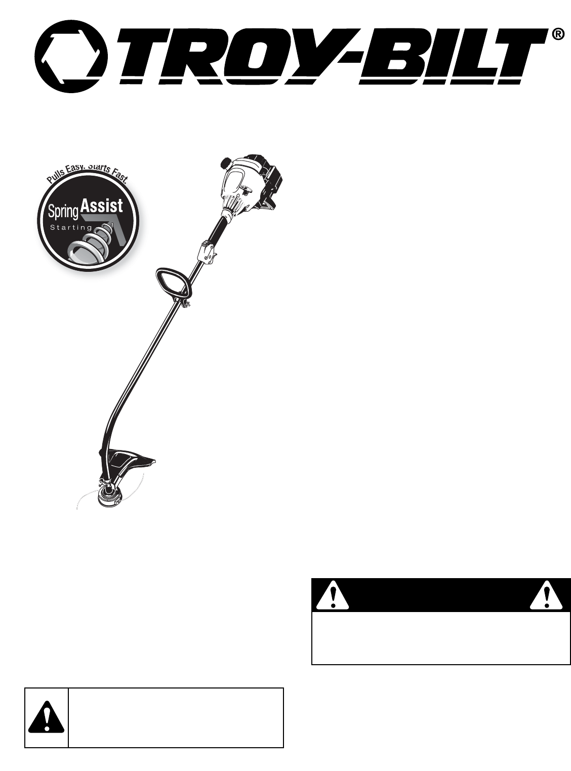
Operator’s Manual Easy. Starts Fa lls st. u P TM 2-Cycle Gasoline Trimmer TB10CS Starting SAVE THESE INSTRUCTIONS For service call 1-800-520-5520 in the United States, or 1-800-668-1238 in Canada to obtain a list of authorized service dealers near you. For more details about your unit, visit our website at www.troybilt.com. DO NOT RETURN THE UNIT TO THE RETAILER. PROOF OF PURCHASE WILL BE REQUIRED FOR WARRANTY SERVICE. THIS PRODUCT IS COVERED BY ONE OR MORE U.S. PATENTS. OTHER PATENTS PENDING.
RULES FOR SAFE OPERATION • IMPORTANT SAFETY INSTRUCTIONS • READ ALL INSTRUCTIONS BEFORE OPERATING WARNING: When using the unit, you must follow the safety rules. Please read these instructions before operating the unit in order to ensure the safety of the operator and any bystanders. Please keep these instructions for later use. • Read the instructions carefully. Be familiar with the controls and proper use of the unit.
RULES FOR SAFE OPERATION SAFETY AND INTERNATIONAL SYMBOLS This operator's manual describes safety and international symbols and pictographs that may appear on this product. Read the operator's manual for complete safety, assembly, operating and maintenance and repair information. SYMBOL MEANING SYMBOL MEANING • SAFETY ALERT SYMBOL • ON/OFF STOP CONTROL Indicates danger, warning or caution. May be used in conjunction with other symbols or pictographs.
KNOW YOUR UNIT APPLICATIONS As a trimmer: • Cutting grass and light weeds. • Edging • Decorative trimming around trees, fences, etc.
ASSEMBLY INSTRUCTIONS INSTALL AND ADJUST THE D-HANDLE 1. Push the D-handle down onto the shaft housing and push it on the boom (Fig. 1). The squared bolt hole in the handle is to the right. Guard Mounting Bracket Washer Shaft Grip Shaft Housing D-Handle Wing Nut Square Bolt Fig. 3 Tighten 3. Minimum 6 inches (15.24 cm) Wing Nut Put the washer on the bolt, then screw the wing nut onto the bolt and tighten. Figure 4 shows the installation process from underneath the unit.
STARTING / STOPPING INSTRUCTIONS WARNING: Operate this unit only in a wellventilated outdoor area. Carbon monoxide exhaust fumes can be lethal in a confined area. Stop/Off (O) Start/On ( I ) WARNING: Avoid accidental starting. Make sure you are in the starting position when pulling the starter rope (Fig. 8). To avoid serious injury, the operator and unit must be in a stable position while starting. Throttle Control STARTING INSTRUCTIONS 1. Mix gas with oil. Fill fuel tank with fuel/oil mixture.
OPERATING INSTRUCTIONS HOLDING THE TRIMMER WARNING: Always wear eye, hearing, foot and body protection to reduce the risk of injury when operating this unit. Before operating the unit, stand in the operating position (Fig. 9).
OPERATING INSTRUCTIONS 6. 7. 8. On/Off Stop Control Fig. 12 3. c) Tighten the wing nut and bolt. Rotate the edge guide. Accomplish this by loosening its wing nut slightly and turning the guide to the left (when facing the unit away from the engine). Turn the guide about 90˚ (Fig. 13) or until it resembles the position shown in Figure 14. Line up the cutting line with the edge of the sidewalk.
MAINTENANCE AND REPAIR INSTRUCTIONS MAINTENANCE SCHEDULE Bolt WARNING: To prevent serious injury, never Bump Knob™ perform maintenance or repairs with unit running. Always service and repair a cool unit. Disconnect the spark plug wire to ensure that the unit cannot start.
MAINTENANCE AND REPAIR INSTRUCTIONS Single Line Installation Go To Step 8 for SplitLine™ Installation 6. Take approximately 20 feet (6 m) of new trimming line, loop it into two equal lengths. Insert each end of the line through one of the two holes in the inner reel (Fig. 20). Pull the line through the inner reel so that the loop is as small as possible. Holding Slots Fig. 23 Loop 13.
MAINTENANCE AND REPAIR INSTRUCTIONS AIR FILTER MAINTENANCE Removing the Air Filter/Muffler Cover WARNING: To avoid serious personal injury, always turn your unit off and allow it to cool before you clean or service it. 1. Place the choke lever in Position 2. NOTE: The choke lever must be in Position 2 (Fig. 7) to remove the air filter/ muffler cover. 2. Remove the four (4) screws securing the air filter/muffler cover (Fig. 25). Use a flat blade or T20 Torx bit screwdriver. 3.
MAINTENANCE AND REPAIR INSTRUCTIONS 8. 9. Replace the two screws you removed in Step 2 and tighten them securely. Reinstall the air filter/muffler cover. WARNING: If the exhaust deflector assembly is not tightened securely, it could fall off causing damage to the unit and possible serious personal injury. CARBURETOR ADJUSTMENT The idle speed of the engine is adjustable through the air filter/muffler cover (Fig. 31). NOTE: Careless adjustments can seriously damage your unit.
TROUBLESHOOTING ENGINE WILL NOT START CAUSE ACTION Empty fuel tank Fill fuel tank with properly mixed fuel Primer bulb wasn't pressed enough Press primer bulb fully and slowly 10 times Engine is flooded Squeeze the trigger and pull the starter rope Old or improperly mixed fuel Drain gas tank and add fresh fuel mixture Fouled spark plug Replace or clean the spark plug Plugged spark arrestor Clean or replace spark arrestor he outside temperature is below 40º F Pull the starter rope up to 10-15
SPECIFICATIONS ENGINE* Engine Type ................................................................................................................................................................. Air-Cooled, 2-Cycle Stroke............................................................................................................................................................................ 1.25 in. (31.75 mm) Displacement....................................................................................
California / EPA Emission Control Warranty Statement Your Warranty Rights and Obligations The California Air Resources Board, the Environmental Protection Agency and Troy-Bilt LLC (Troy-Bilt) are pleased to explain the emission control system warranty on your 2005 and later small off-road engine. New small off-road engines must be designed, built and equipped to meet stringent anti-smog standards.
MANUFACTURER’S LIMITED WARRANTY FOR: The limited warranty set forth below is given by Troy-Bilt LLC (“Troy-Bilt”) with respect with new merchandise purchased and used in the United States, its possessions and territories. Troy-Bilt warrants this product against defects in material and workmanship for a period of two (2) years commencing on the date of original purchase and will, at its option, repair or replace, free of charge, any part found to be defective in material or workmanship.
Manuel de L'utilisateur Easy. Starts Fa lls st. Pu TM Starting TABLE DES MATIÈRES Service technique . . . . . . . . . . . . . . . . . . . . . . . . . . . . . .F1 Consignes de sécurité . . . . . . . . . . . . . . . . . . . . . . . . . . .F2 Informations sur l'huile et le carburant . . . . . . . . . . . . . .F3 Familiarisez-vous avec votre appareil . . . . . . . . . . . . . . .F4 Instructions de montage . . . . . . . . . . . . . . . . . . . . . . . . .F5 Instructions de démarrage et d'arrêt . . . . . . . .
CONSIGNES DE SÉCURITÉ • IMPORTANTES CONSIGNES DE SÉCURITÉ • LIRE TOUTES LES INSTRUCTIONS AVANT UTILISATION • Veuillez lire les instructions avec soin. Familiarisez-vous avec les commandes et l'utilisation correcte de cet appareil. • N'utilisez pas l'appareil si vous êtes fatigué, malade ou sous l'effet de l'alcool, de drogues ou de médicaments. • Les enfants et adolescents de moins de 15 ans ne doivent pas utiliser l'appareil exceptés les adolescents assistés d'un adulte.
CONSIGNES DE SÉCURITÉ SYMBOLES DE SÉCURITÉ ET INTERNATIONAUX Ce manuel de l'utilisateur décrit les symboles et pictogrammes de sécurité et internationaux pouvant apparaître sur ce produit. Consultez le manuel de l'utilisateur pour les informations concernant la sécurité, le montage, le fonctionnement, l'entretien et les réparations. SYMBOLE SIGNIFICATION SYMBOLE • SYMBOLE ALERTE DE SÉCURITÉ Indique un danger, un avertissement ou une mise en garde.
FAMILIARISEZ-VOUS AVEC VOTRE APPAREIL APPLICATIONS Utilisation comme désherbeuse : • Coupe d'herbe et de mauvaises herbes légères. • Coupe de bordures • Tailler autour des arbres, des clôtures, etc.
INSTRUCTIONS DE MONTAGE INSTALLATION ET RÉGLAGE DE LA POIGNÉE EN D 1. Enfoncez la poignée en D sur le corps de l'arbre afin de l’incliner vers la prise de l'arbre (Fig. 1). Le trou de boulon carré de la poignée se trouve à droite. 2. De l’intérieur de l’écran de l’accessoire de coupe, poussez le boulon carré dans le trou jusqu’à ce que l’extrémité filetée dépasse de la patte d’attache de l’écran (Fig. 3).
INSTRUCTIONS DE DÉMARRAGE ET ARRÊT AVERTISSEMENT : n’utiliser l’outil qu’à l’extérieur, dans un endroit bien aéré. Les émanations d’oxyde de carbone dans un endroit confiné peuvent être mortelles. Stop/Arrêt (O) Démarrage/ Allumage (I) AVERTISSEMENT: évitez tout démarrage accidentel. Tenez-vous en position de démarrage lorsque vous tirez sur la corde de démarrage (Fig. 8). L'opérateur et l'appareil doivent tous deux être en position stable pour éviter des blessures graves.
MODE D’EMPLOI TENUE DE LA DÉSHERBEUSE AVERTISSEMENT : portez toujours des protections (yeux, oreilles, pieds et corps) pour diminuer les risques de blessures durant l'utilisation de l'appareil. Avant de faire marcher l'appareil, tenez-vous en position de fonctionnement (Fig. 9). Vérifiez les points suivants: • L'opérateur porte une visière et des vêtements appropriés. • Le bras droit est légèrement plié et la main tient l'arbre par sa prise. • Le bras gauche est droit et la main tient la poignée en D.
MODE D’EMPLOI UTILISATION DU COUPE-BORDURE POUR TAILLER LES BORDURES Pour utiliser correctement le guide bordure pour tailler les bordures entre les pelouses et les trottoirs ou autres surfaces, suivez les instructions suivantes : 1. Assurez-vous que l'appareil est bien éteint. 2. Ajustez la poignée en forme de D: a) Dévissez l'écrou à oreilles qui attache la poignée en D à l'arbre. Consultez Ajustement et installation de la poignée en D pour plus de renseignements.
ENTRETIEN ET RÉPARATIONS PROGRAMME D'ENTRETIEN L'entretien doit respecter la fréquence indiquée dans le tableau ci-dessous. Il doit également faire partie de toute mise au point saisonnière. REMARQUE : certaines procédures d'entretien nécessitent des compétences ou des outils particuliers. Si vous n'êtes pas sûr de pouvoir les entreprendre, emmenez votre appareil dans un atelier, chez un technicien ou un concessionnaire agréé spécialisé dans les réparations de moteurs d’outils mécaniques de plein air.
ENTRETIEN ET RÉPARATIONS Installation du fil simple Pour l’installation du SplitLineMC, passez à l’étape 8. 6. Découpez environ 6 m (20 pi) de fil neuf et faites-en deux boucles de longueurs égales. Insérez chaque extrémité de fil dans l'un des deux trous du moulinet (Fig. 20). Tirez le fil à travers le moulinet pour que la boucle soit le plus petit possible. Fentes de retenue Fig. 23 Boucle Fig. 20 7. Enroulez les fils en couches uniformes serrées sur le moulinet (Fig. 21).
ENTRETIEN ET RÉPARATIONS Levier d'étranglement bleu Vis Vis Fig. 25 Nettoyage du filtre à air Nettoyez et relubrifiez le filtre à air à toutes les 10 heures de fonctionnement. C'est l'un des éléments les plus importants pour l'entretien. Tout manquement à l’entretien du filtre à air peut entraîner une baisse de performances ou causer des dégâts permanents à votre moteur. 1. Retirez le couvercle du filtre à air/silencieux. Voir Retrait du couvercle du filtre à air/silencieux. 2.
ENTRETIEN ET RÉPARATIONS RÉGLAGE DU CARBURATEUR Le régime ralenti du moteur est réglable par le couvercle du filtre à air/silencieux (Fig. 31). 3. Remplacez toute bougie fendillée, encrassée ou sale. Réglez l'écartement à 0,5 mm (0,020 po) à l'aide d'une jauge d'épaisseur (Fig. 32). MISE EN GARDE : évitez de sabler, gratter ou nettoyer les électrodes car de la saleté dans le moteur pourrait endommager le cylindre. Vis de réglage de ralenti 4.
DÉPANNAGE LE MOTEUR REFUSE DE DÉMARRER CAUSE Réservoir de carburant vide La poire d'amorçage n'a pas été pressée assez fort Moteur noyé Carburant vieux ou mal mélangé Bougie encrassée Pare-étincelles colmaté La température extérieure est inférieure à 40°F La température extérieure est supérieure à 90°F SOLUTION Remplissez-le de carburant bien mélangé.
CARACTÉRISTIQUES MOTEUR* Type de moteur ................................................................................................................................................... Refroidi par air, 2-temps Course......................................................................................................................................................................... 31,75 mm (1,25 po) Cylindrée .............................................................................................
Garantie portant sur les normes antipollution de l'EPA et la California Vos droits et obligations en vertu de cette garantie Le California Air Resource Board, la Environmental Protection Agency et Troy-Bilt LLC (Troy-Bilt) ont le plaisir de présenter la garantie du dispositif antipollution des petits moteurs à usage tout-terrain datant de 2005 et au-delà. Les nouveaux petits moteurs à usage tout-terrain doivent être conçus, construits et équipés pour être conformes aux strictes normes anti-smog.
GARANTIE LIMITÉE DU FABRICANT POUR: La garantie limitée énoncée ci-après est accordée par Troy-Bilt LLC (« Troy-Bilt ») et concerne les marchandises neuves achetées et utilisées aux États-Unis, ainsi que dans leurs possessions et territoires.
Manuel del Dueño/Operador Easy. Starts Fa lls st. u P TM Starting INDICE DE CONTENIDOS Llamadas a apoyo al cliente . . . . . . . . . . . . . . . . . . . . . .E1 Normas para una operación segura . . . . . . . . . . . . . . . .E2 Información del aceite y del combustible . . . . . . . . . . . .E3 Conozca su unidad . . . . . . . . . . . . . . . . . . . . . . . . . . . . .E4 Instrucciones de ensamble . . . . . . . . . . . . . . . . . . . . . . .E5 Instrucciones de arranque y apagado . . . . . . . . . . . . . .
NORMAS PARA UNA OPERACION SEGURA • IMPORTANTE INFORMACION DE SEGURIDAD • LEA TODAS LAS INSTRUCCIONES ANTES DE LA OPERACION • Lea todas las instrucciones con cuidado. Conozca bien los controles y el uso correcto de la unidad. • No opere esta unidad si está cansado, enfermo, o bajo los efectos del alcohol, drogas o medicamentos. • Los niños y los adolescentes menores de 15 años no deben operar las unidades, excepto por los adolescentes guiados por un adulto. • Inspeccione la unidad antes de utilizarla.
NORMAS PARA UNA OPERACION SEGURA SIMBOLOS DE SEGURIDAD E INTERNACIONALES Este manual del operador describe los símbolos y figuras de seguridad e internacionales que pueden aparecer en este producto. Lea el manual del operador para obtener información completa acerca de la seguridad, ensamble, operación y mantenimiento y reparación. SIMBOLO SIGNIFICADO SIMBOLO SIGNIFICADO • SIMBOLO DE ALERTA DE SEGURIDAD Indica peligro, advertencia o precaución. Puede ser utilizado junto con otros símbolos o figuras.
CONOZCA SU UNIDAD APLICACIONES Como recortadora; Palanca azul de EZ-Start™ • Corte de césped y hierbas delgadas • Recorte de bordes • Recorte decorativo alrededor de árboles, cercos, etc.
INSTRUCCIONES DE ENSAMBLE 2. INSTALACIÓN Y AJUSTE DE LA MANIJA EN D 1. Desde el interior del protector del accesorio de corte, empuje el perno cuadrado a través del orificio hasta que el extremo con roscas sobresalga a través del soporte de montaje de la guardera (Fig. 3). Empuje la manija en D hacia abajo sobre el bastidor del eje de modo que la manija se incline hacia adelante del mango del eje (Fig. 1). El orificio del perno cuadrado de la manija queda hacia la derecha.
INSTRUCCIONES DE ARRANQUE Y APAGADO ADVERTENCIA: Use esta unidad sólo en un área exterior bien ventilada. Los gases de escape de monóxido de carbono pueden ser letales en un área cerrada. Parado/ Apagado (O) Arranque/ Encendido (I) ADVERTENCIA: Evite los arranques accidentales. Colóquese en posición de inicio cuando tire de la cuerda de arranque (Fig. 8). El operador y la unidad deben estar en una posición estable al arrancar la unidad para evitar graves lesiones personales. INSTRUCCIONES DE ARRANQUE 1.
INSTRUCCIONES DE OPERACION COMO SOSTENER EL RECORTADOR ADVERTENCIA: Use siempre protección para sus ojos, audición, pies y cuerpo para reducir el riesgo de una lesión al operar esta unidad. Antes de operar esta unidad, párese en posición de operación (Fig. 9). Verifique lo siguiente: • El operador tiene protección ocular y ropa adecuada. • El brazo derecho está levemente doblado, y la mano está sosteniendo el mango del eje. • El brazo izquierdo está recto, y la mano está sosteniendo la manija.
INSTRUCCIONES DE OPERACION CÓMO USAR EL RECORTADOR DE BORDES PARA RECORTAR LOS BORDES Siga estas instrucciones para usar debidamente la guía de bordes para recortar los bordes entre el césped y las aceras o demás superficies: 1. Cerciórese de que la unidad esté completamente apagada. 2. Ajuste el mango en forma de D. a) Afloje la tuerca de aletas que une el mango en forma de D con el eje. Para información específica, consulte Ajuste e Instalación del mango en forma de D.
INSTRUCCIONES DE MANTENIMIENTO Y REPARACION NOTA: Algunos procedimientos de mantenimiento pueden requerir el uso de herramientas o habilidades especiales. Si no está seguro acerca de estos procedimientos, lleve su unidad a un establecimiento de reparación, persona o distribuidor de servicio autorizado que arregle motores para uso fuera de la carretera. PROGRAMA DE MANTENIMIENTO Estos procedimientos requeridos para el mantenimiento deben ser realizados con la frecuencia indicada en la tabla.
INSTRUCCIONES DE MANTENIMIENTO Y REPARACION NOTA: La línea SplitLine™ sólo puede usarse con el carrete interior con los orificios ranurados. La línea individual puede usarse en cualquier tipo de carrete interior. Use la Figura 19 para identificar el carrete interior que usted tiene. Para usar SÓLO con línea individual Para usar con SplitLine™ o línea individual Orificios ranurados Lazo Fig. 22 Fig. 19 NOTA: Use siempre la longitud correcta de línea cuando instale la línea de corte en la unidad.
INSTRUCCIONES DE MANTENIMIENTO Y REPARACION INSTALACIÓN DE UN CARRETE PREBOBINADO 1. Sostenga la bobina exterior con una mano y desenrosque la perilla percusiva en sentido antihorario (Fig. 16). Inspeccione el perno dentro del botón de tope para verificar que se mueva con libertad. Cambie el botón de tope si está dañado. 2. Saque el carrete interior viejo de la bobina exterior (Fig. 17). 3. Saque el resorte del carrete interior viejo (Fig. 17). 4. Coloque el resorte en el carrete interior nuevo.
INSTRUCCIONES DE MANTENIMIENTO Y REPARACION MANTENIMIENTO DEL PARACHISPAS NOTA: El flujo de las emisiones puede ser en una dirección solamente: APARTÁNDOSE del motor. Preste mucha atención a cómo se ensambla el silenciador, de modo que lo pueda volver a armar exactamente como está. El no hacerlo así dañará a la unidad y pudiera causar lesiones personales graves. 1. Quite el filtro de aire / tapa del silenciador. Ver Remoción de la Tapa del Filtro / Silenciador. 2. Localice el silenciador, pero no lo quite.
INSTRUCCIONES DE MANTENIMIENTO Y REPARACION CAMBIO DE LA BUJIA DE ENCENDIDO Use una bujía de encendido Champion RDJ7Y (o similar). La separación correcta es de 0,5 mm (0,020 pulgadas). Retire la bujía luego de cada 25 horas de operación e inspeccione su estado. 1. Apague el motor y espere que se enfríe. Tome el alambre de la bujía con firmeza y sáquelo de la bujía de encendido. 2. Limpie alrededor de la bujía de encendido.
RESOLUCION DE PROBLEMAS EL MOTOR NO ARRANCA CAUSA El tanque de combustible está vacío La bombilla de cebado no fue oprimida lo suficiente El motor está inundado El combustible es viejo o está mal mezclado La bujía de encendido está arruinada Parachispas obstruido La temperatura exterior es por debajo de 4º C (40º F) La temperatura exterior es de más de 32º C (90º F) ACCIÓN Llene el tanque con combustible bien mezclado Oprima la bombilla de cebado total de 10 veces Use el procedimiento de arranque Drene el
ESPECIFICACIONES MOTOR* Tipo de motor.......................................................................................................................... Enfriado por aire, de 2 ciclos Carrera ............................................................................................................................................... 31,75 mm (1,25 pulg.) Desplazamiento ...................................................................................................................................
NOTAS E16
Declaración de Garantía de Control de Emisiones de la EPA / California Sus Derechos y Obligaciones de la Garantía La Junta de Recursos del Aire de California, la Agencia de Protección Ambiental y Troy-Bilt LLC (Troy-Bilt) se complacen en explicar la garantía del sistema de control de emisiones para su pequeño motor para uso fuera de la carretera del 2005 y posterior.
PARTS LIST ENGINE PARTS - TB10CS 2-CYCLE GAS TRIMMER - ENGINE 3 36 4 18 5 16 17 6 7 11 20 2 1 3 36 13 8 9 10 37 50 12 21 14 38 19 35 23 15 39 24 48 32 31 28 25 46 49 36 29 26 30 44 47 27 42 34 45 43 33 41 40 Item Part No.
PARTS LIST BOOM AND TRIMMER PARTS - TB10CS 2 CYCLE TRIMMER 7 2 8 1 3 10 1 4 11 6 9 5 11 13 14 12 Item Part No.
GARANTÍA LIMITADA DEL FABRICANTE PARA: La garantía limitada establecida a continuación es dada por TroyBilt LLC (“Troy-Bilt”) con respecto a mercancía nueva que sea comprada y usada en los Estados Unidos, sus posesiones y territorios.