
Operating Guide

Controls & Operation
3
8
Headlight (If Equipped)
The headlight is located on the upper center
of the control panel and is ON when the snow
thrower is running.
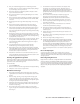
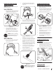
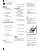
Engine Controls
If your model has an electric starter, stand in
the operator’s position and refer to Figure 3-2
for the location of the Engine Controls. If your
model does not have an electric starter, stand
in the operator’s position and refer to Figure 3-3
for the location of the Engine Controls.
Choke Lever
Primer
Safety Key
Electric Starter
Outlet †
† — If Equipped
Electric Starter
Button †
Figure 3-2
Choke Lever
Primer
Safety Key
Figure 3-3
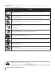
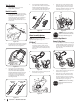
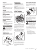
Snow thrower controls and features are
described below and illustrated in Figure 3-1.
NOTE: This Operator’s Manual covers several
models. Snow thrower features may vary by
model. Not all features in this manual are
applicable to all snow thrower models and the
snow thrower depicted may differ from yours.
NOTE: All references to the left or right side
of the snow thrower are from the operator’s
position. Any exceptions will be noted.
Auger
When engaged, the auger rotation draws snow
into the auger housing and throws it out the
chute assembly. Rubber paddles on the auger
also aid in propelling the snow thrower as they
come in contact with the pavement.
Auger Control Lever
Located on the upper handle, the auger
control lever is used to engage and disengage
drive to the auger. Squeeze the auger control
lever against the upper handle to engage the
auger; release it to disengage.
Shave Plate
The shave plate maintains contact with the
pavement as the snow thrower is propelled,
allowing snow close to the pavement’s surface
to be discharged.
Recoil Starter Handle
The recoil starter handle is used to manually
start the engine.
Chute Assembly
(See Insets for Specific
Chute Types)
Recoil Starter Handle
Auger
Auger Control Lever
Headlight †
Chute Tilt Control †
Chute Rotation Control †
Shave Plate
Drift Cutter †
Chute
Handle †
Lower 2-Way Chute †
Chute Rotation
Control
Upper 2-Way Chute †
Chute Assembly
Chute Tilt Control
Chute Rotation
Control
E-Z Chute™ †
Figure 3-1
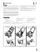
E-Z Chute™ (If Equipped)
Rotate the chute assembly to the left or right
using the chute handle. The pitch of the chute
assembly controls the angle at which the
snow is thrown. Stop the engine, remove the
safety key and loosen the wing knob on the
side of the chute assembly before pivoting the
upper portion of the chute assembly upward
or downward. Retighten the knob once the
desired position has been achieved.
Lower 2-Way Chute (If Equipped)
Rotate the chute assembly to the left or right
using the chute rotation control. The pitch of
the chute assembly controls the angle at which
the snow is thrown. Stop the engine, remove the
safety key and loosen the wing knob on the side
of the chute assembly before pivoting the chute
upward or downward. Retighten the knob once
the desired position has been achieved.
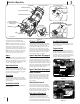
Upper 2-Way Chute (If Equipped)
Chute Tilt Control
The chute tilt control is located to the right
of the control panel and controls the angle/
distance that snow is thrown. Pull back on
the chute tilt control to increase the angle/
distance and push forward to decrease the
angle/distance.
Chute Rotation Control
The chute rotation control is located in the
center of the control panel and controls the
direction snow is thrown. Depress the button
and rotate the chute rotation control to the
right to turn the chute to the right and rotate
to the left to turn the chute to the left.
Drift Cutters (If Equipped)
The drift cutters are designed for use in deep
snow. Their use is optional for normal snow
conditions. Maneuver the snow thrower so that
the cutters penetrate a high standing snow drift
to assist snow falling into the augers for throwing.
† — If Equipped