
Operating Guide

7Section 2 — ASSembly & Set-Up
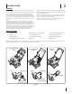
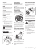
2. Using the hex washer screws (a), install
the chute rotation control assembly. See
Figure 2-12.
(a)
(a)
(a)
(a)
Figure 2-12
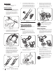
3. Remove the screw (a) and hex lock nut (b)
from the universal joint. See Figure 2-13.
(a)
(b)
Figure 2-13
NOTE: Make sure the chute is facing
forward when installing the universal joint.
4. Install the universal joint on the end of
the chute rod as shown in Figure 2-13.
NOTE: Be sure the holes in the universal
joint line up with the holes in the chute
rod. You may have to activate the trigger
to allow you to line up the holes.
5. Secure the universal joint with the hex
lock nut (b) and screw (a) removed in
Step 3. See Figure 2-13.
6. Slide the rubber bellow over the
universal joint. See Figure 2-14.
Figure 2-14
STOP
STOP! Continue to Installing
the Recoil Starter Handle onto
the Upper Handle (page 7).
Installing the Chute Rotation
Control (If Equipped)
NOTE: Refer to Figure 2-1 and continue to your
applicable chute style.
Lower 2-Way Chute
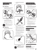
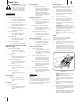
1. Remove the hex lock nut (a) and machine
screw (b) from the chute rotation control
assembly. See Inset I in Figure 2-10.
(a)
(a)
(b)
(b)
I
II
Figure 2-10
2. Place the chute rotation control
assembly onto the chute rotation rod,
align the holes and secure with the
hex lock nut (a) and machine screw (b)
removed in Step 1. See Inset II in Figure
2-10.
STOP
STOP! Continue to Installing
the Recoil Starter Handle onto
the Upper Handle (page 7).
Upper 2-Way Chute
1. Remove the hex washer screws (a) from
the back of the handle (two on each
side). See Figure 2-11.
(a)
(a) (a)
(a)
Figure 2-11
Installing the Recoil Starter
Handle onto the Upper Handle
1. Remove the eye bolt and handle knob
from the manual bag.
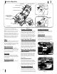
2. Place the eye bolt (a) and handle knob (b)
on the upper handle as shown in Inset I
in Figure 2-15. Do not fully tighten the
hardware until instructed to do so.
(b)
(a)
I
II
Figure 2-15
NOTE: The opening of the eye bolt (a)
should face toward the back of the snow
thrower.
3. Slowly pull the recoil starter handle up
towards the eye bolt (a).
4. Slip the recoil starter rope into the
eye bolt (a) from the back of the snow
thrower. See Inset II in Figure 2-15.
5. Securely tighten the eye bolt (a) and
handle knob (b).
Installing the Drift Cutters
(If Equipped)
1. Remove the carriage bolts (a) and flange
lock nuts (b) from the drift cutters.
2. Install the drift cutters and secure with
the carriage bolts (a) and flange lock
nuts (b) removed in Step 1. See Figure 2-16.
(b)
(a)
Figure 2-16
Adding Fuel & Oil
Refer to the Engine Operator’s Manual for
information on adding fuel and oil.