
Operating Guide

6 Section 2 — ASSembly & Set-Up
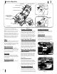
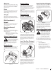
3. Align the holes in the chute base with
the three tabs (b) in the lower chute as
shown in Figure 2-8, Inset I. Secure the
chute base with the hex washer screws (a)
removed in Step 2. See Figure 2-8.
(a)
(a)
(a)
I
(b)
(b)
(b)
Figure 2-8
STOP
STOP! Continue to Installing
the Recoil Starter Handle onto
the Upper Handle (page 7).
Lower 2-Way Chute &
Upper 2-Way Chute
1. If not already done, install the chute plug (a)
onto the chute (b) as shown in Figure 2-9.
Be certain that the plug is aligned in the
channel on the chute and that the tabs
snap into place.
(a)
(b)
Figure 2-9
2. Remove the hex washer screws (a) in the
chute base. See Figure 2-7.
3. Align the holes in the chute base with
the three tabs (b) in the lower chute as
shown in Figure 2-8, Inset I. Secure the
chute base with the hex washer screws (a)
removed in Step 2. See Figure 2-8.
STOP
STOP! Continue to Installing
the Chute Rotation Control
(page 7).
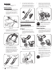
4. On models with adjustable handles,
place the handle in the desired position
and then install wing knobs (a) and
carriage bolts (b) in the appropriate hole
and secure the handle. See Figure 2-5.
(a)
(b)
Figure 2-5
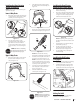
Chute Assembly Options
NOTE: Refer to Figure 2-1 and continue to your
applicable chute style on pages 6-7.
E-Z Chute™
1. Place the chute handle (a) onto the
chute (b) as shown in Figure 2-6. Be
certain that the handle is aligned in the
channel on the chute and the tabs snap
into place.
(a)
(a)
(b)
(b)
Figure 2-6
2. Remove the hex washer screws (a) in the
chute base. See Figure 2-7.
(a)
(a)
(a)
Figure 2-7
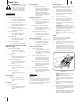
Tools Required
• Adjustable Wrench or Socket Set
• Phillips Head Screwdriver
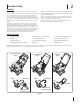
Handle Assembly
1. Remove the wing knob (a) and carriage
bolt (b) from the top of the lower handle.
See Figure 2-2. It is not necessary to
remove the shoulder screw and flange
lock nut below the wing knob and
carriage bolt unless the handle is loose
in the carton.
(a)
(b)
(a)
(b)
Figure 2-2
2. Pivot the upper handle into the operating
position. Be sure not to pinch any of the
cables in the process. See Figure 2-3.
(a)
(a)
(b)
(b)
Figure 2-3
3. See Figure 2-4. On models with an
adjustable handle (a), proceed with
Step 4. On models without adjustable
handle (b), tighten the hardware removed
in Step 1 to secure the handle in place.
See Figure 2-3. For models without
an adjustable handle (b), continue to
Installing the Chute.
(b)
(a)
Adjustable
Handle
Non-Adjustable
Handle
Figure 2-4