
Operating Guide


Assembly & Set-Up
3
5
Contents of Carton
• Log Splitter (1) • Operator’s Manual (1) • Engine Operator’s Manual (1)
NOTE: This Operator’s Manual covers several models.
Features may vary by model. Not all features in this
manual are applicable to all models and the model
depicted may differ from yours.
IMPORTANT: A minimum of two people are
recommended to assemble this unit.
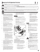
WARNING! Do not remove the beam
support or attempt to remove the
machine from the crate until after you
have completed all assembly steps. See
Figure 3-1.
Figure 3-1
WARNING! Use extreme caution when
unpacking this machine. It is very heavy
and may require additional people to
assist in removing the log splitter from
the crate.
NOTE: All references in this manual to the left or
right side of the log splitter are from the operating
position only. Exceptions, if any, will be specified.
Unpacking & Assembling the Log Splitter
Tools Required
• Safety Glasses
• Two 9/16” Wrenches (or Adjustable Wrenches)
• Leather Safety Gloves
• Wire Cutters, Tin Snips or Utility Knife
• Pry Bar and/or Claw Hammer
• Hole Punch
Crate Disassembly
1. Use a pry bar or claw hammer to loosen and
remove the top of the crate.
2. Use a pry bar or claw hammer to remove the
four sides of the crate, beginning with the
short sides (or front and back side of the log
splitter) and then the long sides (or left and
rides side of the log splitter. Set the sides of
the crate aside to avoid injury.
3. Remove the large plastic cover, if present, and
discard.
WARNING! Do NOT remove any supports
or cut any straps securing the log splitter
to the crate at this time. Only remove
straps and/or supports when instructed to
do so.
4. Inspect the bottom of the crate for any
protruding staples or wood splinters and
remove.
5. Remove and set aside any loose parts included
with the log splitter.
Repositioning the Tongue Tube
For shipping purposes, the tongue tube is secured
to the log splitter frame near its center. To reposition
it, refer to Figure 3-2 and Figure 3-3 and proceed as
follows:
Figure 3-2
1. Cut the straps securing the tongue tube to the
beam support.
2. Remove the pair of hex screws and flange nuts
securing the tongue tube to the log splitter
frame. See A in Figure 3-2.
3. Carefully slide the tongue tube toward the
front of the machine. See B in Figure 3-2.
4. Pull the beam lock outward, line it up with
the hole in the beam bracket and release the
beam lock. See C in Figure 3-3.
Figure 3-3
NOTE: To assist in aligning the holes in the
tongue tube with the holes in the beam
bracket, a hole punch can be used.
5. Fasten the tongue tube to the frame by
reinstalling the two hex screws removed in
Step 1 and tightly securing with the two flange
lock nuts. See D in Figure 3-3.
Positioning the Jack Stand
CAUTION: Do not attempt to move the
log splitter off of the crate base until after
the jack stand has been positioned
downward.
The jack stand is shipped in the transport position. It
must be repositioned prior to fully removing the log
splitter from the crate.
1. Remove the spring clip and clevis pin and
pivot the jack stand toward the ground into
the operating position.
2. Secure the jack stand in position with the
clevis pin and the spring clip. See Figure 3-4.
Clevis Pin
Spring Clip
Figure 3-4
3. Carefully pry the small block of wood from the
base of the crate and position it beneath the
jack stand. See Figure 3-5.
Figure 3-5