
Operating Guide


10 Section 5— Service
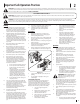
2. Remove the three flange lock nuts and hex
screws that secure the pump to the coupling
shield. Two flange lock nuts and hex screws
are at the bottom corners and one is in the top
center. See Figure 5-5.
.090
.020
Flange Lock Nuts
Hex Screw
Set Screw
Figure 5-5
3. Remove the pump.
4. Loosen the set screw on the pump coupling
half and remove the coupling half.
5. Rotate the engine by slowly pulling the starter
handle until the engine coupling half set
screw is at the bottom. Loosen the set screw
using an allen wrench and slide the coupling
half off the engine shaft.
6. Slide the new engine coupling half onto the
engine shaft until the end of the shaft is flush
with the inner portion of the coupling half.
(There must be space between the end of the
engine support bracket and the coupling half).
Tighten the set screw.
7. Install the nylon “spider” onto the engine
coupling half.
8. Install the pump coupling half and key on the
pump shaft. Rotate the coupling half until the
set screw faces down. Do not tighten the set
screw.
9. Align the pump coupling half with the nylon
“spider” by rotating the engine using the
starter handle. Slide the coupling half into
place while guiding the three hex screws
through the holes in the pump support
bracket.
10. Secure with the nuts removed in Step 2 of this
section.
11. Set .020” to .090” of a clearance/gap between
the nylon “spider” and the engine coupling
half by sliding a feeler gauge between the
nylon “spider” and the engine coupling
half and moving the pump coupling half as
needed. Install the set screw and torque to 78
in-lbs to secure the pump coupling half. See
Figure 5-5.
NOTE: Make certain the proper clearance/gap
is obtained before tightening the set screw.
12. Reconnect the spark plug.
Hose Clamps
Check the clamps on the return hose before each
use and check the clamps on the suction hose once
a season.
Hydraulic Filter
Change the hydraulic filter every 50 hours of
operation. Use a 10 micron hydraulic filter only. Order
part number 723-0405.
Beam & Splitting Wedge
Lubricate the top, sides and bottom of the beam and
where it comes into contact with the splitting wedge
with engine oil before each use.
Off-Season Storage
If the log splitter will not be used for more than 30
days, prepare for storage as follows:
WARNING! Never store the machine with
fuel in the fuel tank inside of building
where fumes may reach an open flame or
spark, or where ignition sources are
present such as hot water and space
heaters, furnaces, clothes dryers, stoves,
electric motors, etc.
1. Refer to the Engine Operator’s Manual packed
with your log splitter for information on the
off-season storage of the engine.
2. Clean the log splitter thoroughly.
NOTE: The use of pressure washers or a garden
hose to clean the splitter is not recommended.
They may cause damage to the bearings or
the engine. The use of water to clean the log
splitter will result in a shortened life and reduce
serviceability.
3. Wipe the machine with an oiled rag to prevent
rust, especially on the wedge, beam and
horizontal bracket.
4. Store the log splitter in a clean, dry area. Do
not store it next to corrosive materials, such as
fertilizer.
NOTE: If storing in an unventilated or metal
storage shed, be certain to rustproof the
equipment by coating it with a light oil or
silicone.Flexible Pump Coupler
The flexible pump coupler is a nylon “spider” insert,
located between the pump and the engine shaft.
Over time, the coupler will harden and deteriorate.
Replace the coupler if you detect vibration or noise
coming from the area between the engine and
the pump. If the coupler fails completely, you will
experience a loss of power.
NOTE: Never hit the engine shaft in any manner, as a
blow will cause permanent damage to the engine.
1. Disconnect the spark plug wire and ground it
against the engine.