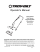
Operator’s Manual Self Propelled Yard Vacuum Chipper/Shredder/ Vacuum/Hose Model Number 24A-070F766 IMPORTANT: READ SAFETY RULES AND INSTRUCTIONS CAREFULLY Warning: This unit is equipped with an internal combustion engine and should not be used on or near any unimproved forestcovered, brush-covered or grass-covered land unless the engine’s exhaust system is equipped with a spark arrester meeting applicable local or state laws (if any).
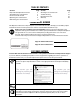
TABLE OF CONTENTS Content Important Safe Operation Practices Assembling Your Yard Vacuum Know Your Yard Vacuum Operating Your Yard Vacuum Maintaining Your Yard Vacuum Page 3 5 8 9 11 Content Servicing Your Yard Vacuum Trouble Shooting Illustrated Parts List Warranty Page 12 15 16 20 FINDING MODEL NUMBER This Operator’s Manual is an important part of your new Yard Vacuum. It will help you assemble, prepare and maintain the unit for best performance. Please read and understand what it says.
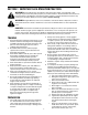
SECTION 1: IMPORTANT SAFE OPERATION PRACTICES WARNING: This symbol points out important safety instructions which, if not followed, could endanger the personal safety and/or property of yourself and others. Read and follow all instructions in this manual before attempting to operate this machine. Failure to comply with these instructions may result in personal injury. When you see this symbol - heed its warning.
10. Keep all guards, deflectors and safety devices in place and operating properly. 11. Keep your face and body back and to the side of the chipper chute while feeding material into the machine to avoid accidental kickback injuries. 12. Never operate this machine without good visibility or light. Always be sure of your footing and keep a firm hold on the handles. 13. Do not operate this machine on a gravel surface. 14. Do not operate this machine while under the influence of alcohol or drugs. 15.
SECTION 2: ASSEMBLING YOUR YARD VACUUM IMPORTANT: This unit is shipped without gasoline or oil in the engine. Be certain to service engine with gasoline and oil as instructed in the separate engine manual before operating your machine. NOTE: Reference to right or left hand side of the Yard Vacuum is observed from the operating position. This Yard Vacuum has been completely assembled at the factory, except for the handle, bag, and blower chute. These parts are shipped loose in the carton.
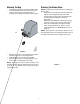
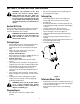
Attaching The Handle Attaching The Hose Assembly • • Remove the hairpin clips from the handle brackets and remove the carriage screws and wing nuts from the lower handle. See Figure 3A. Slide hose adapter of hose assembly into the base adapter located on the left front of the Yard Vacuum. See Figure 4. Figure 4 • Rope Guide Cable Tie Wing Nut • • Handle Knobs Pull spring loaded pin out on the base and align pin with the first hole (closest to the end of the tube) in the hose adapter.
Attaching The Bag • Attaching The Blower Chute Grasp bag handle with one hand and slide locking rod on mounting bracket with other hand toward engine. Use the end of mounting bracket as leverage when sliding the locking rod. See Figure 6. NOTE: The bag must be removed before installing the blower chute. • Grasp blower chute with one hand and slide locking rod on mounting bracket with other hand toward engine. Use the end of mounting bracket as leverage when sliding the locking rod. See Figure 7.
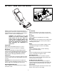
SECTION 3: KNOW YOUR YARD VACUUM Nozzle/Hose Vac Lever Figure 8 Hose Assembly Read this operator’s manual and safety rules before operating your Yard Vacuum. Compare the illustrations in Figure 8 with your unit to familiarize yourself with the location of various controls and adjustments. Used as an alternative to the nozzle to vacuum yard waste such as leaves or pine needles in hard to reach places.
SECTION 4: OPERATING YOUR YARD VACUUM WARNING: The operation of the Yard Vacuum can result in foreign objects being thrown into the eyes, which can damage your eyes severely. Always wear the safety glasses provided with this unit or eye shields before chipping or blowing and while performing any adjustments or repairs. • To Empty Bag • • Gas And Oil Fill-Up • • Service the engine with gasoline and oil as instructed in the separate engine manual packed with your Yard Vacuum. Read instructions carefully.
Using the Nozzle Vacuum WARNING: Do not at any time make any adjustments without first stopping engine and disconnecting spark plug wire. Place nozzle/hose vac lever in the top position on the nozzle to vacuum through nozzle. See Figure 10. Using the Hose Assembly • • • Place nozzle/hose vac handle in the bottom position on the nozzle to redirect vacuum to the hose assembly. See Figure 11. The spring loaded pin must be in the second hole of the hose adapter to operate the hose assembly.
SECTION 5: MAINTAINING YOUR YARD VACUUM PRODUCT 0h ou Ev rs er y1 00 ho ur On s ce as ea so Be n for es tor ag e ou rs Ev er y5 Ev er y2 Be fo SCHEDULE re e MAINTENANCE 5h ac h us e Customer Responsibilities SERVICE DATES Lubricate Wheels Lubricate Nozzle Levers Lubricate Locking Rod Lubricate Nozzle/Hose Handle Check Chipper Blade ENGINE Change Oil Check Air Filter Clean Engine Check Spark Plug Maintenance WARNING: Always stop engine and disconnect spark plug wire before cleaning, lubrica
SECTION 6: SERVICING YOUR YARD VACUUM Drive Control Cable Adjustment Adjust the drive control cable if the yard vacuum does not self propel with the drive control engaged, or if the unit hesitates while the engine maintains the same speed after approximately 20 hours of use.
• • Remove self-tapping screw on right side of unit that attaches to the fail screen. See Figure 16. • Remove the shoulder screws, thrust washers, and bell washers that go through the pivot arms to the front support brace. The front support brace and lock nut can be removed at this time as well. Remove the four screws on the upper housing that secure the nozzle cover. See Figure 18.
• • Using a 3/16” allen wrench, remove the flat head cap screws that hold the chipper blade to the impeller. These screws are accessible through the opening created when the chipper chute was removed earlier. See Figure 20. Flat Head Cap Screw • Reassemble by performing the previous steps in the opposite order and manner of removal. Tighten blade screws to 210 - 250 in-lbs. NOTE: Make certain chipper blade is reassembled with the sharp edge facing upward. See Figure 22.
SECTION 7: TROUBLESHOOTING Problem Engine fails to start Engine runs erratic Cause Remedy 1. Spark plug wire disconnected. 2. Fuel tank empty or stale fuel. 3. Throttle control lever not in correct starting position. 4. Choke not in CHOKE position. (If Equipped) 5. Engine (if equipped with a primer) not primed properly. 6. Blocked fuel line. 7. Faulty spark plug. 1. Connect wire to spark plug. 2. Fill tank with clean, fresh gasoline. 3. Move throttle lever to FAST position. 1. Spark plug wire loose.