
Operating Guide
10 SECTION 3— ASSEMBLY & SET-UP
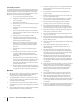
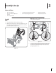
Chute Assembly (If Equipped w/ 4-Way Chute Control)
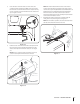
Remove cotter pin, wing nut and hex screw from chute
control head. Remove clevis pin and bow-tie cotter pin
GSPNDIVUFTVQQPSUCSBDLFU4FF'JHVSF
Chute Control Head
Chute
Chute Support
Bracket
Chute Base
Figure 3-10
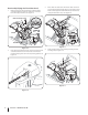
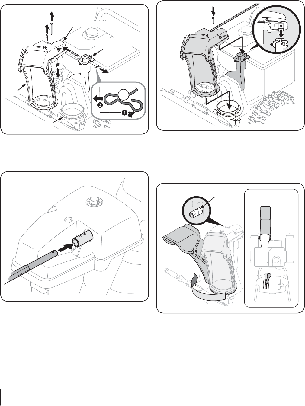
2. Insert chute control rod into chute control head. Push rod
as far into chute control head as possible, keeping the
IPMFTJOUIFSPEQPJOUJOHVQXBSE4FF'JHVSF
Figure 3-11
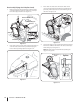
3. Place chute onto chute base and ensure chute control
rod is positioned under the handle panel. Install hex bolt
previously removed, but do not secure with wing nut at
UIJTUJNF4FF'JHVSF
Figure 3-12
Squeeze the trigger on the joystick and rotate the chute by
hand to face forward. The holes in the chute control input
XJMMCFGBDJOHVQ4FF'JHVSF
NOTE: The chute will not rotate without squeezing the
trigger on the joystick.
Top View
Chute Control
Input
Figure 3-13