4BGF 0QFSBUJPO 1SBDUJDFT t 4FU 6Q t 0QFSBUJPO t .BJOUFOBODF t 4FSWJDF t 5SPVCMFTIPPUJOH t 8BSSBOUZ OPERATOR’S MANUAL NOTE: Unit shown with optional electric chute directional control Two-Stage Snow Thrower — Storm 3090XP WARNING READ AND FOLLOW ALL SAFETY RULES AND INSTRUCTIONS IN THIS MANUAL BEFORE ATTEMPTING TO OPERATE THIS MACHINE. FAILURE TO COMPLY WITH THESE INSTRUCTIONS MAY RESULT IN PERSONAL INJURY. TROY-BILT LLC, P.O. BOX 361131 CLEVELAND, OHIO 44136-0019 Printed In USA Form No.
1 To The Owner Thank You Thank you for purchasing a Troy-Bilt Snow Thrower. It was carefully engineered to provide excellent performance when properly operated and maintained. in this manual may not be applicable to all models. We reserve the right to change product specifications, designs and equipment without notice and without incurring obligation. Please read this entire manual prior to operating the equipment. It instructs you how to safely and easily set up, operate and maintain your machine.
Important Safe Operation Practices 2 WARNING! This symbol points out important safety instructions which, if not followed, could endanger the personal safety and/or property of yourself and others. Read and follow all instructions in this manual before attempting to operate this machine. Failure to comply with these instructions may result in personal injury. When you see this symbol.
Safe Handling of Gasoline 5. To avoid personal injury or property damage use extreme care in handling gasoline. Gasoline is extremely flammable and the vapors are explosive. Serious personal injury can occur when gasoline is spilled on yourself or your clothes which can ignite. Wash your skin and change clothes immediately. Never run an engine indoors or in a poorly ventilated area. Engine exhaust contains carbon monoxide, an odorless and deadly gas.
Clearing a Clogged Discharge Chute Hand contact with the rotating impeller inside the discharge chute is the most common cause of injury associated with snow throwers. Never use your hand to clean out the discharge chute. To clear the chute: SHUT THE ENGINE OFF! 2. 8BJU TFDPOET UP CF TVSF UIF JNQFMMFS CMBEFT IBWF stopped rotating. 3. Always use a clean-out tool, not your hands. Maintenance & Storage Never tamper with safety devices. Check their proper operation regularly.
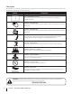
Safety Symbols This page depicts and describes safety symbols that may appear on this product. Read, understand, and follow all instructions on the machine before attempting to assemble and operate. Symbol Description READ THE OPERATOR’S MANUAL(S) Read, understand, and follow all instructions in the manual(s) before attempting to assemble and operate WARNING— ROTATING BLADES Keep hands out of inlet and discharge openings while machine is running.
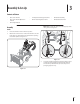
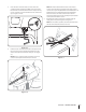
3 Assembly & Set-Up Contents of Carton t One Snow Thrower t Two Replacement Auger Shear Pins t One Chute Assembly t One Snow Thrower Operator’s Manual t One Product Registration Card t One Chute Control Rod t One Engine Manual NOTE: Make certain the cables are seated properly in the roller guides. See Figure 3-2. Assembly Handle 1MBDF UIF TIJGU MFWFS JO UIF 'PSXBSE QPTJUJPO 2.
3. Chute Assembly (If Equipped w/ Electric Chute Control) Remove cotter pin, wing nut and hex screw from chute control head. Remove clevis pin and bow-tie cotter pin from chute support bracket. See Figure 3-3. Place chute onto chute base and ensure chute control rod is positioned under the handle panel.
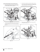
5. NOTE: The hole furthest from the chute control head is used to achieve further engagement of the chute control rod into the coupler if required. Refer to the Maintenance & Adjustments section for Chute Control Rod adjustment. The hole closest to the chute control head is used for manual movement of the chute assembly if required. Refer to the Controls & Features section. Insert the other end of the chute control rod into the coupler below the handle panel.
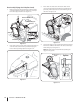
Chute Assembly (If Equipped w/ 4-Way Chute Control) 3. Remove cotter pin, wing nut and hex screw from chute control head. Remove clevis pin and bow-tie cotter pin GSPN DIVUF TVQQPSU CSBDLFU 4FF 'JHVSF Place chute onto chute base and ensure chute control rod is positioned under the handle panel. Install hex bolt previously removed, but do not secure with wing nut at UIJT UJNF 4FF 'JHVSF Chute Control Head Chute Support Bracket Chute Chute Base Figure 3-12 Figure 3-10 2.
5. Rotate the joystick to the one o’clock position so that the silver indicator arrow on the pinion gear below the control QBOFM GBDFT VQXBSE 4FF 'JHVSF 7. Push the chute control rod toward the control panel until the hole in the rod lines up with the hole in the chute control input closest to the chute control head and insert UIF DPUUFS QJO 4FF 'JHVSF NOTE: The second hole is used to achieve further engagement of the chute control rod into the pinion gear if required.
Tire Pressure Set-Up WARNING: Under any circumstance do not exceed manufacturer’s recommended psi. Equal tire pressure should be maintained at all times. Excessive pressure when seating beads may cause tire/rim assembly to burst with force sufficient to cause serious injury. Refer to side wall of tire for recommended pressure. Shear Pins A pair of replacement auger shear pins and bow tie cotter pins are included with your snow thrower.
NOTE: If you choose to operate the snow thrower on a gravel surface, keep the skid shoes in position for maximum clearance between the ground and the shave plate. 3. While standing in the operator’s position (behind the snow thrower), engage the auger. Allow the auger to remain engaged for approximately ten TFDPOET CFGPSF SFMFBTJOH UIF BVHFS DPOUSPM 3FQFBU UIJT several times. 5.
4 Controls and Features Electric Chute Directional Control † Drive Control Shift Lever Auger Control Heated Grips Headlight Manual Chute Directional Control † Steering Trigger Control Chute Assembly Chute Clean Out Tool Skid Shoe Augers † If Equipped Figure 4-1 Snow thrower controls and features are described below and illustrated in Figure 4-1 (Unit shown above with optional electric chute directional control).
Auger Control Steering Trigger Controls The auger control is located on the left handle. Squeeze the control grip against the handle to engage the augers and start snow throwing action. Release to stop. Drive Control / Auger Clutch Lock The left and right wheel steering trigger controls are located on the underside of the handles. t Squeeze the right control to turn right. t Squeeze the left control to turn left.
4-Way Chute Directional Control (If so Equipped) 4. Grasp the indented portion of the chute control rod and manually rotate the chute assembly to the right or to the left. See Figure 4-3. The 4-way chute directional control is located on the left side of the dash panel. t To change the direction in which snow is thrown, squeeze the button on the joy-stick and pivot the joy-stick to the right or to the left. t To change the angle/distance which snow is thrown, pivot the joy-stick forward or backward.
5 Operation Starting and Stopping the Engine Replacing Shear Pins Refer to the Engine Operator’s Manual packed with your snow thrower for instructions on starting and stopping the engine. The augers are secured to the spiral shaft with shear pins and bow-tie cotter pins. If the auger should strike a foreign object or ice jam, the snow thrower is designed so that the pins may shear. If the augers will not turn, check to see if the pins have sheared. See Figure 5-2.
6 Maintenance & Adjustments Maintenance Lubrication Engine Gear Shaft Refer to the Engine Operator’s Manual. The gear (hex) shaft should be lubricated at least once a season or after every twenty-five (25) hours of operation. Shave Plate and Skid Shoes Allow the engine to run until it is out of fuel. 2. Carefully pivot the snow thrower up and forward so that it rests on the auger housing.
Auger Shaft Drive Control At least once a season, remove the shear pins from the auger shaft. Spray lubricant inside the shaft and around the spacers and the flange bearings found at either end of the shaft. See Figure When the drive control is released and in the disengaged “up” position, the cable should have very little slack. It should NOT be tight.
Auger Control Chute Directional Control (If Equipped w/ 4-Way Chute Control) Refer to the Assembly and Set-up section for instructions on adjusting the auger control cable. To adjust the chute control rod, proceed as follows: Remove the cotter pin from the hole closest to the chute assembly on the chute rotation assembly. 2. Pull out the chute control rod until the hole in it lines up with the second hole in the chute rotation assembly. See 'JHVSF 3.
7 Service 3. Belt Replacement Roll the auger belt off the engine pulley. See Figure 7-2. Auger Belt To remove and replace your snow thrower’s auger belt, proceed as follows: Allow the engine to run until it is out of fuel. Do not attempt to pour fuel from the engine. Remove the key to avoid unintended starting. 2.
Loosen and remove the shoulder bolt which acts as a belt LFFQFS 4FF 'JHVSF 8. Replace the auger belt by following instructions in reverse order. NOTE: Do not forget to reinstall the shoulder bolt and reconnect the spring to the frame after installing a replacement auger belt.
8 Troubleshooting Problem Cause Remedy Choke not in CHOKE position. Move choke to CHOKE position. 2. Spark plug wire disconnected. 2. Connect wire to spark plug. 3. Fuel tank empty or stale fuel. 3. Fill tank with clean, fresh gasoline. Engine not primed. Prime engine as instructed in the Operation section. 5. Faulty spark plug. 5. Clean, adjust gap, or replace. Key not in ignition on engine. Insert key fully into the switch. 7.
9 Replacement Parts Component Part Number and Description 954-04195A 954-04201A Auger Drive Belt Wheel Drive Belt 684-04153C 935-04054 Friction Wheel Assembly Friction Wheel Rubber 925-1629 Lamp, 12V 738-04124A 714-04040 Shear Pin, 1.
10 Attachments & Accessories The following attachments and accessories are available for your Troy-Bilt snow thrower. Phone (800) 828-5500 for information regarding compatibility, price and availability (have your full model number and serial number ready).
MANUFACTURER’S LIMITED WARRANTY FOR The limited warranty set forth below is given by Troy-Bilt LLC with respect to new merchandise purchased and used in the United States and/or its territories and possessions, and by MTD Products Limited with respect to new merchandise purchased and used in Canada and/or its territories and possessions (either entity respectively, “Troy-Bilt”). b.
.FEJEBT JNQPSUBOUFT EF TFHVSJEBE t $POöHVSBDJØO t 'VODJPOBNJFOUP t .BOUFOJNJFOUP t 4FSWJDJP t 4PMVDJØO EF QSPCMFNBT t (BSBOUÓB MANUAL DEL OPERADOR /05" 6OJEBE EF NVFTUSB BSSJCB DPO FM DPOUSPM EJSFDDJPOBM EFM DBOBM PQDJPOBM FMÏDUSJDB .ÈRVJOB RVJUBOJFWF EF EPT FUBQBT 4UPSN 91 "%7&35&/$*" -&" : 4*(" 50%"4 -"4 */4536$$*0/&4 %& &45& ."/6"- "/5&4 %& 10/&3 &/ '6/$*0/".*&/50 &45" .«26*/" 4* /0 3&41&5" &45"4 */4536$$*0/&4 16&%& 13070$"3 -&4*0/&4 1&340/"-&4 TROY-BILT LLC, P.O.
1 Al propietario Gracias Gracias por comprar una Troy-Bilt máquina quitanieve. La misma ha sido diseñada cuidadosamente para brindar excelente rendimiento si se la opera y mantiene correctamente. las especificaciones de los productos, los diseños y el equipo estándar sin previo aviso y sin generar responsabilidad por obligaciones de ningún tipo. Por favor lea todo este manual antes de operar el equipo. Le indica cómo configurar, operar y mantener la máquina con seguridad y fácilmente.
Medidas Importantes de Seguridad 2 ¡ADVERTENCIA! La presencia de este símbolo indica que se trata de instrucciones importantes de seguridad que se deben respetar para evitar poner en peligro su seguridad personal y/o material y la de otras personas. Lea y siga todas las instrucciones de este manual antes de poner en funcionamiento esta máquina. Si no respeta estas instrucciones puede provocar lesiones personales. Cuando vea este símbolo.
Nunca intente realizar ajustes mientras el motor está en marcha excepto en los casos específicamente recomendados en el manual del operador. 7. Deje que el motor y la máquina se adapten a la temperatura exterior antes de comenzar a sacar la nieve. Manejo seguro de la gasolina Para evitar lesiones personales o daños materiales tenga mucho cuidado cuando trabaje con gasolina. La gasolina es sumamente inflamable y sus vapores pueden causar explosiones.
20. Para encender el motor, jale de la cuerda lentamente hasta que sienta resistencia, luego jale rápidamente. El repliegue rápido de la cuerda de arranque (tensión de retroceso) le jalará la mano y el brazo hacia el motor más rápido de lo que usted puede soltar. El resultado pueden ser huesos rotos, fracturas, hematomas o esguinces. Si se presentan situaciones que no están previstas en este manual, sea cuidadoso y use el sentido común.
Símbolos de Seguridad Esta página describe los símbolos y figuras de seguridad internacionales que pueden aparecer en este producto. Lea el manual del operador para obtener la información terminada sobre seguridad, reunirse, operación y mantenimiento y reparación. Símbolo Descripción LEA EL MANUAL DEL OPERADOR (S) Lea, entienda, y siga todas las instrucciones en el manual (es) antes de intentar reunirse y funcionar.
3 Montaje y Configuración Contenido de la caja t Una máquina quitanieve t Dos pasadores de cuchilla de barrena de repuesto t Una tarjeta para registrar el producto t Un Manual del Operador de la Máquina Quitanieve t Varilla hexagonal t Canal de montaje t Un Manual del Motor Montaje Manija Coloque la palanca de cambios en la posición de avance ' 2.
Montaje del canal (En su Caso w / Control Eléctrico Chute) 1. 3. Lugar en la tolva tolva de base y garantizar la varilla hexagonal está situado bajo el asa del panel. La cabeza seguro control del canal de soporte de soporte del canal con el pasador de horquilla y pajarita pasador extraído en el paso 1. Vea la Figura 3-5. 4. Finalizar la cabeza de asegurar el control del conducto con la instalación de tornillo hexagonal y tuerca de mariposa. Vea la Figura 3-6.
5. NOTA: El agujero más alejado de la cabeza de control tolva se utiliza para lograr una mayor implicación de la varilla de control del canal en el engranaje de piñón si es necesario. Consulte la sección Mantenimiento y Ajustes para el ajuste de varilla de control del canal. Insertar el otro extremo de la varilla de control del canal en el acoplador por debajo del panel de asa. Asegúrese de alinear la parte plana de la varilla y el extremo plano del acoplador.
Montaje del Canal (En su Caso w / Control del Canal de Cautro Direcciones) 1. 3. Lugar en la tolva tolva de base y garantizar la varilla hexagonal está situado bajo el asa del panel. Instalar el perno hexagonal previamente eliminado, pero no seguro con tuerca de mariposa en este momento. Vea la Figura 3-12. 4. Apriete el disparador en la palanca de control y gire el canal manualmente para que mire hacia delante. Los orificios en el cabezal de control del canal estarán mirando hacia arriba.
5. Gire la palanca de control hasta que la flecha indicadora plateada en el engranaje del piñón por debajo del panel de control señale hacia arriba. Vea la Figura 3-14. 7. Empuje la varilla hacia el panel de control hasta que el orificio en la varilla hexagonal se alinee con el orificio en la entrada de control del canal lo más cerca posible del cabezal de control del canal e inserte el pasador de chaveta. Vea la Figura 3-16. Figura 3-14 Nota: La palanca de control girará ligeramente hacia la derecha.
Nota: Para más suave funcionamiento, los cables deben estar a la izquierda de la varilla hexagonal. Configuración Pasadores de Cuchilla Su máquina quitanieve trae un par de pasadores de cuchilla de la barrena y pasadores de chaveta con unión curva de reemplazo. Guárdelos en el panel de instrumentos de la máquina hasta que los necesite. Vea la Figura 3-18. Presión de los Neumáticos ADVERTENCIA: Bajo ninguna circunstancia no excedan del fabricante recomienda psi.
Para ajustar las zapatas antideslizantes: 1. Afloje las cuatros tuercas hexagonales (dos en cada lado) y los pernos del carro. Mueva las zapatas antideslizantes a la posición deseada. Vea la Figura 3-20. 4. Deje la barrena engranada durante aproximadamente diez (10) segundos antes de soltar el control de la barrena. Repita esta operación varias veces. 5. Con el control del regulador en la posición FAST (dibujo de un conejo), y la barrena en posición desengranada arriba, camine al frente de la máquina.
4 Controles y Características Control de Transmisión Palanca de Cambios Control direccional del canal Eléctrico † Control de la Barrena Faro Delantero Agarre Termico Control direccional del canal manual † Control Disparador del Manejo Montaje del Canal Herramienta de Limpieza del Canal Zapatas Antideslizantes Barrenas † Si está Equipado Figura 4-1 Los controles y características de la máquina quitanieve se describen a continuación y se ilustran en la Figura 4-1 (Unidad de muestra arriba con el cont
Control de la Barrena Control Disparador del Manejo El control de la barrena está ubicado en la manija izquierda. Apriete la empuñadura de control contra la manija para engranar las barrenas y empiece a quitar nieve. Suelte para que se detenga. Control de Transmisión / Traba del Embrague de la Barrena Los controles izquierdos y derechos del disparador del manejo de la rueda están situados en el superficie inferior de las manijas.
Control del Canal de Cautro Direcciones (Si está Equipado) 3. Vuelva a insertar el pasador a través de este agujero y la barra de control del canal, como se muestra en la Figura 4-2 . 4. Agarre la parte dentada de la barra de control tolva y girar manualmente el conjunto de la canaleta hacia la derecha o hacia la izquierda. Ver la Figura 4-3. El control direccional del canal está ubicado del lado izquierdo del panel de instrumentos.
5 Funcionamiento Encendido del Motor y Detención del Motor Reemplazo de los Pasadores de Cuchilla Consulte el Mantenimiento del Motor para motores embalado con la máquina para ver el Encendido del Motor y Detención del motor. Las barrenas están ajustadas al eje espiral con dos pasadores de cuchilla y pasadores de chaveta. Si la barrena golpeara un objeto extraño o un trozo de hielo, la máquina quitanieve ha sido diseñada para que los pasadores se quiebren.
6 Mantenimiento y Ajustes Mantenimiento Lubricación Motor Eje de Engranaje Consulte el Mantenimiento del Motor para motores embalado con la máquina para ver el mantenimiento del motor. El eje de engranaje (hexagonal) se debe lubricar al menos una vez por temporada o tras cada 25 horas de operación. Placa de Raspado y Zapatas Antideslizantes 1. Deje que el motor funcione hasta que se acabe el combustible. 2.
Eje de la Barrena 3. Gire el soporte hacia abajo para reducir el juego del cable. Al menos una vez por temporada, quite los pasadores de cuchilla del eje de la barrena. Rocíe lubricante en el interior del eje y alrededor de los separadores y los cojinetes bridados que se encuentran en ambos extremos del eje. Vea la Figura 6-3. 4. Vuelva a apretar la tuerca hexagonal.
Control de la Barrena Consulte la sección Montaje y Configuración para ver las instrucciones del ajuste del cable de control de la barrena. Montaje del Canal Consulte la sección Montaje y Configuración para ver las instrucciones del ajuste del ensamblado del canal de las zapatas antideslizantes. Varilla de Control del Canal (En su Caso w / Control del Canal de Cautro Direcciones) Para ajustar la varilla de control del canal proceda de la siguiente manera: 1.
7 Servicio 3. Cambio de Correa Saque la correa de la barrena de la polea del motor. Vea la Figura 7-2. Correa de la Barrena Para retirar y reemplazar la correa de la barrena de su máquina quitanieve, proceda como se indica a continuación: Deje que el motor funcione hasta que se acabe el combustible. 2. Saque la cubierta plástica de la correa ubicada en el frente del motor. Para ello saque los dos tornillos autorroscantes.
6. NOTA: No olvide volver a instalar el tornillo con reborde y volver a conectar el resorte al marco tras instalar la correa de la barrena de repuesto. Afloje y retire el tornillo con reborde que actúa como guardacorrea. Vea la Figura 7-4. 9. Después de reemplazar la correa de la barrena, realice la prueba de control de barrena en la página 41 para verificar la correa se ajusta correctamente.
Notas 49
8 Solución de Problemas Problema Solución El control del cebador no está en la posición CHOKE (encendido). Ponga el control del cebador en la posición CHOKE (encendido). 2. Se ha desconectado el cable de la bujía. 2. Conecte el cable a la bujía. 3. El depósito de combustible está vacío o el combustible se ha echado a perder. 3. Llene el tanque con gasolina limpia y fresca. El motor no está cebado. Cebe el motor tal como se explicó en la sección Funcionamiento. 5.
Problema La unidad no se autoimpulsa La unidad no descarga la nieve $IVUF OP HJSBS grados Causa Solución El cable del control de transmisión necesita un ajuste. Ajuste el cable del control de transmisión. Consulte la sección Mantenimiento y Ajustes. 2. La correa de transmisión está floja o dañada. 2. Póngase en contacto con un centro de servicio autorizado. 3. La fricción de la rueda desgastada. 3. Vuelva a colocar la rueda de fricción.
9 Piezas de Reemplazo Componente Número de pieza y Descripción " " $PSSFB EF USBOTNJTJØO EF MB CBSSFOB $PSSFB EF USBOTNJTJØO EF MB SVFEB $ .
10 Aditamentos y Accesorios Los siguientes aditamentos y accesorios son compatibles con el máquina quitanieve. Llame (800) 828-5500 para la información con respecto a la compatibilidad, el precio y la disponibilidad (tener su número de modelo completo y número de serie). Número de modelo " " Descripción $PSEØO QSPMPOHBEPS 7 Puños Calentados 0&.
GARANTÍA LIMITADA DEL FABRICANTE PARA La siguiente garantía limitada es otorgada por Troy-Bilt LLC con respecto a nuevos productos adquiridos y utilizados en Estados Unidos y/o sus territorios y posesiones, y por MTD Products Limited con respecto a nuevos productos adquiridos y utilizados en Canadá y/o sus territorios y posesiones (cualquiera de las dos entidades, respectivamente, “Troy-Bilt”). Esta garantía es adicional a la garantía de emisiones aplicables proporcionada con el producto.