IRIS-Config-Manual-1a
Configuration Manual IRIS-Config-Manual-1a Table of contents The IRIS Base module 1 The IRIS system The IRIS configuration program 2 3 Project Create a project 3 3 Unit Create a unit Delete a unit Export Import 3 3 4 4 4 Setup Network setup Radio setup Serial communication setup Timer setup Counter setup Input setup 5 5 7 8 9 9 10 Events Add events Add actions to events I/O events Timer events Counter events Network events Radio events Serial communication events Unit events Message events 11 11 1
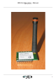
IRIS Configuration - Manual IRIS-Config-Manual-1a 1
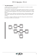
IRIS Configuration - Manual IRIS-Config-Manual-1a The IRIS-system An IRIS-system consists of a group of IRIS-units arranged in a tree structure (see picture below) connected to each other by radio. The top unit is the concentrator in the system and the connection to end-user via, for example, a serial interface, a web-module or a GSM-module. The other units in the system are connected to various electronic equipments or acts as repeaters to enable communication over longer distances.
IRIS Configuration - Manual IRIS-Config-Manual-1a IRIS configuration program The configuration program helps the user to setup an IRIS-system. Project An IRIS-system is two or more IRIS-units communicating with each other, with other electronic equipment and with the end-user. To make it easier to administrate and create an IRIS-system, all the units’ configuration files are stored in the same project folder. Create a project Start with creating a configuration file for each unit that are in the system.
IRIS Configuration - Manual IRIS-Config-Manual-1a Delete a unit Choose ”Delete IRIS unit” under the File menu. Delete IRIS unit: • Choose unit from list and press the “Remove unit” button. Export It is possible to save all or some of the settings for reuse in other unit files. Choose ”Export IRIS unit” under” the File menu. Export: • Check the parameters that are to be saved • Name the file Import It is possible to retrieve settings saved by the export command. Choose ”Import IRIS unit” under” the File menu.
IRIS Configuration - Manual IRIS-Config-Manual-1a Setup For the unit to interact properly with its environment it is vital that the setup is done carefully. Network setup Describes how the IRIS-unit interacts with other IRIS units, closes to it in the system. Alias: Alias is the name of the unit. It makes it easier to identify units in large systems. Upper unit: The unit closes to the IRIS-unit, up the tree structure.
IRIS Configuration - Manual IRIS-Config-Manual-1a Ping times: Ping time is used to detect a lost connection it the network. If there is no radio communication, for a certain time, the unit send a short message to establish contact. The upper unit is, in most cases, responsible to maintain the radio connection. Change ping time • Choose ping time from the list • To change ping time for the upper unit • Press “Change upper unit ping time” button.
IRIS Configuration - Manual IRIS-Config-Manual-1a Radio setup Channel To avoid interference with other systems it is possible to use different radio channels. All IRIS units in the same system most use the same channel setting. • Channel 1-69 is in the 433MHz frequency area • Channel 70-81 is in the 439 MHz frequency area Protocol For now there is only one radio protocol, the IRIS-standard protocol. If there is a need in the future versions of the program it is possible to add other protocol as well.
IRIS Configuration - Manual IRIS-Config-Manual-1a Serial communication setup Any changes in the serial communication setup can have effect on the possibility of future changes of the setting. Baudrate • The baudrate is between 300 and 115200 baud. • Default: • 9600 baud Parity • Uses odd, even or no parity.
IRIS Configuration - Manual IRIS-Config-Manual-1a Timer setup The IRIS-unit has four timers that can be used for generating events. • Resolution: • 100ms • Maximum time: • 4000h Counter setup The IRIS-unit has four counters for that can be used generating events.
IRIS Configuration - Manual IRIS-Config-Manual-1a Input setup An IRIS-unit can have up to six inputs. The inputs can be set to either digital or analogue. Voltage range Different models of the IRIS-unit have different voltage range on there inputs. Digital The input is either high or low. The result is stored in InputA. Lower limit Defines the upper limit for a low level. Upper limit Defines the lower limit for a high level.
IRIS Configuration - Manual IRIS-Config-Manual-1a Events An event occurs when for example, an input that changes value or a timer that reaches its limit. It is possible to add actions to the events to make the IRIS-unit interact with its environment. Add events Events can be turned on and off using the checkbox to the left of the event. Add actions to events An event can have one or more actions.
IRIS Configuration - Manual IRIS-Config-Manual-1a Network events The IRIS-unit is monitoring its the upper unit and its lower units. Unit online The event is generated when one of the nearby units goes online after been offline for a while. Unit offline The event is generated when one of the nearby units goes offline. Radio events Transmitting and receiving packages on the radio generates radio events. Package received A package is received successfully.
IRIS Configuration - Manual IRIS-Config-Manual-1a Message events The IRIS-unit can store twenty different strings of text. Each text can be up to thirty characters long and can include wildcards. An event can be generated by a message that comes via the radio and/or via the serial interface.
IRIS Configuration - Manual IRIS-Config-Manual-1a Actions The IRIS-unit interacts with its environment through different kinds of actions. It could be for example a changed output, an increased counter or a sent message. All created actions are saved in a list. Message actions The IRIS-unit can send predefined messages to all units in the system. The messages are of different types and may include various parameters. Type of message • Message • Normally used for most messages.
IRIS Configuration - Manual IRIS-Config-Manual-1a Output • - • The current value of the specified digital output represented by 0 or 1. Flag • - • The current value of the specified flag represented by 0 or 1. All I/O • • The current digital values of all inputs, outputs and flags.
IRIS Configuration - Manual IRIS-Config-Manual-1a Output and flag actions Changes the values on its own outputs and flags or sends a command to another unit in the system to change its outputs and flags. Create an output and flag action Set the values on outputs and flags and choose a destination. Double click on the bits to change the values.
IRIS Configuration - Manual IRIS-Config-Manual-1a Configuration of the IRIS-unit It is possible to setup all the parameters at the same time, or just some of them. Connect to the IRIS-unit There are different ways to connect the PC to the IRIS-unit. Direct connection via serial interface Connect the PC and the IRIS-unit with a serial cable. Make sure that the serial interface settings are the same on both the PC and the IRIS-unit.
IRIS Configuration - Manual IRIS-Config-Manual-1a Remote connection via radio Connect the PC and the other IRIS-unit with a serial cable. Make sure that the serial interface settings are the same on both the PC and the IRIS-unit. Via a standard IRIS-unit A standard IRIS-unit need to know the identification number of either the IRIS-unit to be setup or another IRIS-unit within the same network. If the standard IRIS-unit already is a part of the network, no more preparations are necessary.
IRIS Configuration - Manual IRIS-Config-Manual-1a 19