
User Manual

©
2016 Escalade Sports
For Customer Service Call 1-888-996-2729
6
All Rights Reserved.
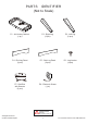
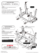
PARTS REQUIRED:
8 pcs - H3 Phillips Round Head Screw
2 pcs - P7 Goal Box with Sensors
STEP 3:
First, feed the sensor plug from each P7 Goal Box with Sensors through each end apron and underneath table support
frames as shown in FIGURE 3 and UNDERNEATH TABLE DIAGRAM. Guide the sensor wires following the path shown
with the arrows in FIGURE 3 and THE UNDERNEATH TABLE DIAGRAM from the goal box to the junction box
Connect P7 Goal Box with Sensors connectors to underneath C3 Junction Box as shown in FIGURE 3.
Secure P7 Goal Box with Sensors onto P1 Air Hockey Cabinet using pilot holes with H3 Phillips Round Head
Screws as shown in FIGURE 3. Tighten, But do not strip out H3 Screws.
P7
H3
P1
P7
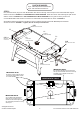
FIGURE 3
C3
Junction Box
(underneath table)
C1
DC Motor
(underneath table)
C2B
BLUE LED Corner Post
C2R
RED LED Corner Post
C2R
RED LED
Corner Post
UNDERNEATH TABLE
C1 DC Motor
GOAL BOX
GOAL BOX
C3 Junction Box
IMPORTANT NOTE:
Be sure to route the goal box sensor
wires thru the support beam cutouts
for correct assembly.
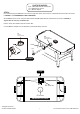
IMPORTANT NOTE:
As you attach the P7 Goal Boxes,
make sure to very lightly pull any
excess wire thru the end apron that
may be blocking the electronic scoring
sensor eyes.
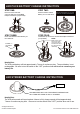
IMPORTANT NOTE:
the connectors that plug into the junction box
will only fit into their slots when turned correctly.
A flashlight may be helpful to achieve this
correct installation.
C2B
BLUE LED Corner Post