
Installation Manual User Manual

8
MoDEl Ft7000 EDU assEMbly FiElD installation GUiDE
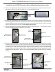
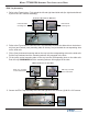
3. Refer to the Figure below. Line up the L-shaped hooks on the UCV Vertical Assembly with the
corresponding openings in two (2) inside vertical I/O mounting rails (trays) on the right side of the
cabinet. The UCV Vertical Assembly should be positioned at vertical location “32” (the number
“31” should be showing just above the mounted location of the UCV Vertical Assembly).
4. Slip the L-shaped hooks through the openings and press DOWN until the two (2) “spring loaded
pins” lock into place.
5. Push the EDU Comms/Power, UCV4 Ground, and EU Bin Present Switch cables through the
opening in the UCV Vertical Assembly (from the back side - see insert).
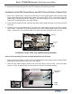
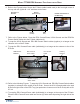
Left Hand Slide Rail Assembly:
1. Refer to the Figures below. Line up the left hand slide rail assembly with corresponding mount-
ing points in the two (2) outside vertical I/O mounting rails (trays) on the left side of the cabinet. It
should be positioned at vertical location “32” (the lowest mounting point on the rails - the number
“31” should be showing just above the mounted location of the Left Slide Rail Assembly).
2. Slip the hooked tabs on the outside edge of the slide rail through the opening in the two (2) out-
side vertical I/O mounting rails (trays) and press DOWN and IN until it locks into place and the
raised edge on the front tab “snaps” into place.
lEFt sliDE rail
assEMbly
UCv vErtiCal
assEMbly
i/o bay
(lowEr)
UCv vErtiCal
assEMbly
Vertical position
“31” (showing)
Vertical mounting rails
(I/O trays)
Spring loaded
pins
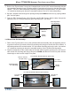
lEFt siDE rail assEMbly MoUntED (oUtsiDE viEw)
lEFt sliDE
rail assEMbly
vErtiCal MoUntinG
rails (i/o trays)
i/o bay
(lowEr)
Vertical position
“31” (showing)
lEFt siDE rail assEMbly MoUntED (insiDE viEw)