
Installation Manual User Manual


11
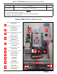
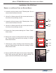
MoDEl Ft7000 EDU assEMbly FiElD installation GUiDE
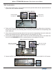
E-CHain
(CablE traCK)
i/o bay
(lowEr)
EDU
tray
UCv vErtiCal
assEMbly
EDU Comms/Power
Cable and Clips
Cable Ty
Hangers
UCV Ground
Cable Connection
EDU Bin Present
Switch Cable
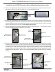
Installation of the EDU Mechanism on the Mounting Tray
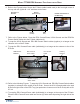
MoUntinG tHE EDU MECHanisM
1. Set the EDU Mechanism on the tray (along the left side of the tray). This will help facilitate the
connection of the cables.
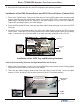
2. Refer to the Figures below. Plug the EDU Bin Present Switch cable (at the output of the E-Chain)
into the “Bins” connector at the EDU (at the forward edge of the EDU Driver PCB). The “Bins”
connector (on the EDU side) should be marked with a WHITE dot and the cable is labeled as
“Bins”).
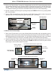
3. The EDU Comms/Power cable is a bundle of two (2) cables (Power and Comms). Plug the
Power cable into the top connector on the rear edge of the EDU Driver PCB (If there is an ex-
tension cable plugged in at this location, plug the Power cable into the extension cable). Plug
the Comms cable into the connector that is third (3rd) from the top on the rear edge of the EDU
Driver PCB.
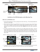
ConnECtinG tHE CoMMs/powEr CablE to tHE EDU
Power connection
at EDU
Comms connection
at EDU
EDU
Extension cable
for Power cable
edu
tray
edu
tray
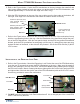
ConnECtinG tHE bin switCH CablE to tHE EDU
BINS
Connection
4. Ty wrap any excess of the EDU Comms/Power cable to the inside right edge of the tray at the
provided tie down point (right side of the tray, neat the rear of the EDU Mechanism).
EDU Mechanism
Driver PCB