Envelope Depository Unit (EDU) Model FT7000 Field Installation Guide TDN 07103-00189 11/2008 Corporate Headquarters: 522 E. Railroad Street Long Beach, MS 39560 Phone: (228) 868-1317 Fax: (228) 868-0437 COPYRIGHT NOTICE © 2008 Triton. All Rights Reserved.
Model FT7000 EDU Assembly Field Installation Guide [This Page Intentionally Left Blank] 2
Model FT7000 EDU Assembly Field Installation Guide Contents Performing the EDU Installation Introduction................................................................................................................................3 Scope..........................................................................................................................................3 Required Parts and Tools...........................................................................................................
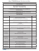
Model FT7000 EDU Assembly Field Installation Guide TOOLS REQUIRED #0, #1, and #2 Phillip screwdrivers Wire Cutters Socket Wrench Kit FT7000 ENVELOPE DEPOSITORY KIT WITH PRESENTER (P/N 06200-08184) 1 FT7000 ENVELOPE DEPOSITORY KIT WITHOUT PRESENTER (P/N 06200-08183) 2 PARTS SUPPLIED PART NUMBERS DESCRIPTION QUANTITY 09200-03002 Depository with Envelope Presenter 1 1 3 (Includes Shutter and Depository Lock Assemblies) 09200-03001 Depository without Envelope Presenter 2 1 (Includes Shutter and Dep
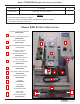
Model FT7000 EDU Assembly Field Installation Guide 03072-00015 6” Ty Wraps 6 03072-00038 Cable Clips - 3/4” Quick Release 2 NOTES 1 2 3 Includes Envelope Supply Unit (ESU) Does not include an Envelope Supply Unit (ESU) or Depository Bracket Includes the Depository Lock Pawl Primary EDU Kit Part Identification 1 Depository with Envelope Presenter (09002-03002) or Depository w/o Envelope Presenter (09002-03001) 2 EDU Tray Assembly (09002-03009) 3 EDU Bin Mounting Bracket Assembly (09200-03006) 4
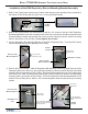
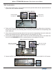
Model FT7000 EDU Assembly Field Installation Guide Installation of the EDU Depository Bin and Mounting Bracket Assembly 1. Refer to the Figure below. Mount two (2) white cable hangers (the openings facing outward) to the bottom of the I/O Bay with two (2) 4 mm x 12 mm pan head screws. I/O Bay (Lower) Cable Hangers 2. Refer to the Figures below.
Model FT7000 EDU Assembly Field Installation Guide 5. Slide the EDU Depository Bin into the EDU Depository Bin Mounting Bracket. Installation of the EDU Comms/Power and UCV4 Ground Cables (Cabinet Side) 1. Refer to the Figure below. Remove the Rear Service Panel (RSP) cables from the white cable hanger (directly below the approximate center of the main GPIO PCB). Loosen and rotate the cable hanger 180 degrees (so the opening in the cable hanger is to the rear of the cabinet).
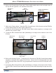
Model FT7000 EDU Assembly Field Installation Guide 3. Refer to the Figure below. Line up the L-shaped hooks on the UCV Vertical Assembly with the corresponding openings in two (2) inside vertical I/O mounting rails (trays) on the right side of the cabinet. The UCV Vertical Assembly should be positioned at vertical location “32” (the number “31” should be showing just above the mounted location of the UCV Vertical Assembly). 4.
Model FT7000 EDU Assembly Field Installation Guide EDU Tray Assembly: 1. Refer to the Figure below. Fully extend the left and right hand slide rails (the right hand slide rail is part of the UCV Vertical Assembly). Slide Rails Extended w/o EDU Tray Horizontal slide mounting slot Vertical slide mounting slot 2. Refer to the Figure below.
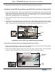
Model FT7000 EDU Assembly Field Installation Guide 6. Refer to the Figures below. Secure the E-Chain (cable bundle track) to the front right corner of the tray with two (2) #4-40 x 1/4” stainless steel screws. UCV Vertical Assembly E-Chain (Cable Track) I/O Bay (Lower) E-Chain Connection to the EDU Tray EDU Tray 7. Refer to the Figures below. Press the EDU Comms/Power, UCV4 Ground, and the EDU Bin Present Switch cables into the E-Chain (cable track). 8.
Model FT7000 EDU Assembly Field Installation Guide E-Chain (Cable Track) UCV Vertical Assembly I/O Bay (Lower) UCV Ground Cable Connection EDU Bin Present Switch Cable EDU Tray EDU Comms/Power Cable and Clips Cable Ty Hangers Installation of the EDU Mechanism on the Mounting Tray Mounting the EDU Mechanism 1. Set the EDU Mechanism on the tray (along the left side of the tray). This will help facilitate the connection of the cables. 2. Refer to the Figures below.
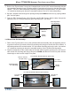
Model FT7000 EDU Assembly Field Installation Guide 5. Refer to the Figures below. Center the EDU mechanism on the tray, between the metal left and right locator guides (raised left and right edges, set at the width of the EDU Mechanism, and located approximately 6” in from the rear edge of the EDU Tray). 6. Slide the EDU Mechanism to the rear of the tray, making sure the front pads on the bottom, left and right front edge of the mechanism slide under the retainer hooks on the tray.
Model FT7000 EDU Assembly Field Installation Guide Installation of the EDU Bezel Removal of the Backer Plate and Existing Bezels 1. Loosen the 4 (four) screws on the 5” Backer plate. Do not remove these screws at this time. 2. Lift the 5 in. Backer plate off of the screws and remove it from the 4 (four) mounting screws. 3. Loosen the 4 (four) screws on the 3” Backer plate. Do not remove these screws at this time. 4. Lift the 3 in.
Model FT7000 EDU Assembly Field Installation Guide Installation of the Backing Plates and Bezels 1. Mount the EDU Bezel at the lowest position possible, with the LED assembly at the top. Secure it with 2 (two) screws in the lowest position. 2. Mount the rain guard to the top of the EDU Bezel with 2 (two) screws. 3. Remount the 5 in. Bezel with 4 (four) screws, but DO NOT tighten. Ensure the Bezel is interlocked with the printer Bezel above and the EDU Bezel below. Cable Guide Rain Guard 4.