
Installation Manual Owner's manual

47
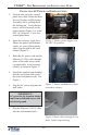
NMD-100 DISPENSING MECHANISM REMOVAL/INSTALLATION
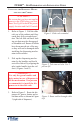
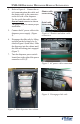
Figure 7. Slide dispenser into cabinet.
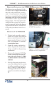
4. Refer to Figure 4. Connect the se-
rial communication data cable and
the shutter cable to the connectors
on the left side of the dispenser .
For the serial data cable, use the
forward -most connector as shown.
The plug is keyed to ensure proper
installation.
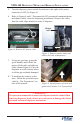
5. Connect the AC power cable to the
dispenser power supply (Figure
5).
6. Disengage the slide rails by lifting
up/down on the locking lever lo-
cated in Figure 6 (both sides). Slide
the dispenser into the cabinet until
the slide rail locking pin is engaged.
(Figure 7)
7. Turn the dispenser power switch
located just to the right of the power
connector to ON (I).
Shutter cable
connector
Serial cable
connector
Figure 4. Shutter and data cable
connectors.
Figure 5. AC power cable connection.
Figure 6. Disengage slide rails.
x
AC power cable connector