AUTOMATED TELLER MACHINE USER MANUAL TDN 07103-00339 CORPORATE HEADQUARTERS: 21405 B STREET LONG BEACH, MS. 39560 PHONE: (800) 259-6672 FAX: (228) 575-3101 © 2014 Triton. All Rights Reserved. TRITON logo is a registered trademark of Triton Systems of Delaware, LLC.
ARGO USER MANUAL DOCUMENT UPDATES February 19, 2013 Original February 21, 2013 Added camera cutout site info March 7, 2013 Added specification table March 28, 2013 Changed card reader cleaning part from 06200-00055 to 05010-00024.
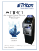
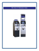
ARGO USER MANUAL The Triton ARGO ATM is a lobby terminal designed for indoor use only. The ARGO line includes models RL1713, RL27XY, and RL63XY. The following sections provide the steps used to understand and operate all functions supported by the ARGO ATM. The ARGO’s larger screens and touch technology simplifies the user experience and operation. TABLE OF CONTENTS Section 1: Introduction ......................................................................................................
ARGO USER MANUAL Section 5: Setup Basics ....................................................................................................39 Introduction ................................................................................................40 Logon .........................................................................................................40 Change Master Password ...........................................................................41 Set Denomination........................
SECTION 1: INTRODUCTION
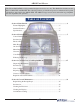
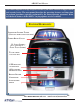
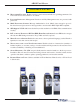
ARGO USER MANUAL Once unit is unpacked, set up, and power restored, you will be asked to set up passwords and security basics. The user manual describes the operating features and shows how to perform procedures typically performed by the owner/operator personnel. Below are the basic features of the ARGO. Varying options are also available. FEATURE HIGHLIGHTS INTEGRATED LIGHTED TOPPER (OPTIONAL HIGH TOPPER AVAILABLE) CAMERA READY CUTOUT 12.
ARGO USER MANUAL Important features of the ARGO series ATM are highlighted in the following list: ► Highly reliable, state-of-the-art operating system PC platform design. The ARGO uses Microsoft® Windows® CE 5.0 operating system with Triton’s X2 technology. Supports Windows file formats for adding custom logos and advertisements. In addition, it features Triton’s completely custom design X2 motherboard. ► Modular architecture eases troubleshooting and servicing.
ARGO USER MANUAL ► High-capacity electronic journal stores transaction details for later printout and analysis. ► Satisfies Americans with Disabilities Act (ADA) specifications for height and access; audio transactions for the visually impaired. Complies with UK accessibility guidelines (DDA) and California access compliance, Title 24. ► Dispenses U.S. and international currency types. ► Camera ready. Cutout at top of fascia is available for a camera to be installed. Camera kit available.
ARGO USER MANUAL STANDARD FEATURES ► MANAGEMENT FUNCTIONS. Enable extensive control and customization of operating parameters. See X-SCALE/X2 CONFIGURATION MANUAL on website. ► PASSWORD PROTECTION. Management Functions and Key Management areas are protected with passwords. ► MAC ENCRYPTION SUPPORT. Message Authentication Code (MAC) data encryption protocol. Provides increased protection for message traffic to and from the ATM. Triple DES compliant. ► SSL Support.
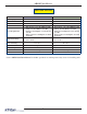
ARGO USER MANUAL SPECIFICATIONS ITEM 7” DISPLAY Operating System RAM Flash Drive TCP/IP Power Requirements • • • • Temperature Range Relative Humidity (non-condensing) LCD Resolution LCD Backlight Modem EMC Standard • • 12.1” DISPLAY Windows CE 5.0 64 MB 128 MB 10 BASE-T/100 BASE-TX with SSL Max current: 3.3A @ 115 VRMS at 60 Hz Voltage: 100-240 VRMS @ 50/60 Hz Idle Power Consumption: 0.
SECTION 2: BASIC OPERATION
ARGO USER MANUAL INTRODUCTION This section describes the basic operation of the terminal. The following topics are covered: 1. CONTROL PANEL LAYOUT. Describes the layout of the terminal’s control panel. 2. KEYPAD OPERATION. Describes the use of the alphanumeric keypads. 3. MENU-BASED OPERATION. Gives a general overview of the terminal display interface. 4. CUSTOMER TRANSACTIONS. Summarizes the actions involved in typical customer transactions.
ARGO USER MANUAL FUNCTION KEYS The eight (8) keys, arranged in two four-key groups on left and right of screen, are called screen function keys. A screen function key is only active when a corresponding function or menu option is present next to that key. The function keys are designated F1 through F8, as shown below. F1 F5 F2 F6 F3 F7 F4 F8 Function key layout on 12.1” screen.
ARGO USER MANUAL ON-SCREEN KEYPAD OPERATION The virtual keypad will be displayed at any time a text entry is required. (Also available by pressing the F-8 function key.) This is used for certain management functions, as well as entering e-mail addresses where receipts can be sent paperless. (Some models will be equipped with paper thermal printers for the option to print receipts.) In models that do not have touch screen entry option, use the keys described below to navigate and enter required data.
ARGO USER MANUAL MENU-BASED OPERATION The terminal operates as a menu driven system. Messages and menu options presented on the LCD display screen guide the user’s actions. The desired menu option is selected by pressing one of the keys located to the left and right of the display. For the purpose of security, many screens time-out after a preset time interval, usually 30 seconds. The time-out length may vary depending on the function being performed.
ARGO USER MANUAL Choosing Management will take you to the password screen. An Error Code of 246 WILL be displayed upon the first start up. You MUST change the master password before any other configuration operations will be allowed. The master password is actually made up of two parts, the ID and the password. The master ID is 00 and cannot be changed. What must be changed is the default master password for ID 00 of 1234.
ARGO USER MANUAL If you do not select a menu choice within 30 seconds, the terminal will automatically default to the Customer Welcome screen (a benefit of this feature is that in the event of a power interruption, the terminal will automatically begin accepting customer transactions shortly after power is restored). CUSTOMER TRANSACTIONS A customer begins a transaction by selecting from the Customer screen options. They insert their ATM card into the card reader of the terminal.
ARGO USER MANUAL ATM transaction processing. The ATM sends the customer transaction request to a processor. A processor is a financial intermediary, such as an Independent Sales Organization (ISO), bank, or other financial institution that provides transactionprocessing services for ATMs. The ATM must be set up with a particular processor before customer transactions can take place. The processor routes the transaction to the appropriate ATM network.
ARGO USER MANUAL VOICE-ENABLED TRANSACTION The terminal provides voice feedback via an integrated output jack, enabling sight-impaired users to plug in a set of headphones and receive spoken instructions to assist them in using the ATM. A raised symbol helps a user locate the headphone jack. The ATM will automatically detect when a headphone has been plugged into the jack, and will immediately switch into voice mode.
ARGO USER MANUAL 7” ARGO with printer and topper 16
SECTION 3: CASSETTE CLOSE / CASH REPLENISHMENT SCDU HCDU MiniMech SDD TDM250 NMD50
ARGO USER MANUAL INTRODUCTION The purpose of this section of the manual is to describe the procedures for cassette closing and replenishment. Information concerning note handling and quality issues are explained where appropriate. DISPENSING MECHANISMS * PLEASE READ * The ARGO Model RL1713 production units are equipped with the MiniMech dispenser and have the shallow cabinet design. The ARGO Model RL27XY (7 inch screen) and the ARGO Model RL63XY (12.
ARGO USER MANUAL NOTE CONDITION The number of rejects can be directly influenced by the technique used to load the cassettes and the quality of the currency. Notes loaded into the mechanism cassettes must be in fit condition if a high level of performance (low reject and failure rate) is expected from the unit. Fit notes are defined as those that do not possess any of the defects listed here: Used Note Defects Adhesive or sticky substances on the surface of the paper.
ARGO USER MANUAL CASSETTE CLOSE PROCEDURES Follow access instructions to enter MANAGEMENT FUNCTIONS. Select TERMINAL CLOSE FUNCTIONS. Select CASSETTE CLOSE. After cassette has been reinserted in the dispenser, press Enter. Select cassette to close. A check mark () identifies which cassette is selected. “A” is selected by default. Press Enter. (Example shows only one cassette available.) Place selected cassette IN SERVICE. “A” will be in service. Press Enter.
ARGO USER MANUAL REPLENISH CASSETTE PROCEDURES SCDU/HCDU 1. Unlock and open the security cabinet door. 2. Remove any rejected notes. The reject compartment is located above the cassette. 3. To remove the note tray, grasp the tray handle, lift slightly, and slide the tray out of the mechanism. Place the note tray on a flat level surface. Use the security key to unlock the cassette, and open the lid. Removing note tray from the dispensing mechanism. Removing rejected notes.
ARGO USER MANUAL 5. Release the packer plate against the notes. 6. Close the lid and lock with the security key. 7. Using the handle, slide the note tray into the dispensing mechanism. Make sure the note tray is fully inserted! 8. HCDU- repeat steps 1-7 for additional cassette. 9. Ensure the Reject door is closed. Close and lock the security container. SDD 1. Unlock/Open the dispenser security door. Grasp the cassette handle and remove the cassette. 2.
ARGO USER MANUAL 3. Slide cassette onto the loading tray. Lift lid to expose the reject tray. Remove any rejected notes. DO NOT recycle rejected notes! Cassette on Loading Tray Lid open to expose Reject Bin 4. Lift the reject tray. Push the packer plate to rear of cassette and latch in place. 5. Count the number of bills that remain in the cassette, if any. Count the number of bills that are being added to the remaining notes.
ARGO USER MANUAL MINIMECH 1. Unlock and open the security cabinet door. 2. To remove the note tray, grasp the tray handle and slide the tray out of the mechanism. Place note tray on a flat level surface. 3. Remove any rejected notes. The reject compartment is located nearest the handle side of the tray. Removing note tray from the dispensing mechanism. Removing rejected notes.
ARGO USER MANUAL TDM250 1. Unlock and open the security cabinet door. 2. To gain access to the cassettes, pull the dispenser slide tray out to its fully extended position, then pull the springloaded locking pin on the underside of the slide tray. 3. Slowly turn the tray clockwise 180° so that the cassettes can be accessed from the front.
ARGO USER MANUAL 1. Move the packer plate to the rear of the cassette (toward the handle). Note: The packer plate action will depend on the type of cassette in use. Some cassettes require you to maintain pressure on the packer plate as needed while loading notes. Other cassettes use a locking mechanism to hold the packer plate in the loading position.
ARGO USER MANUAL 2. Unlock the tray using the supplied key. Flip the top back to gain access to the reject compartment. 3. Remove any notes in the reject compartment. 4. Close and lock the reject tray. Remove the key. Slide the cassette back into its compartment in the dispensing mechanism. Make sure the reject cassette is fully inserted! You will feel the cassette snap securely into the catches.
ARGO USER MANUAL NMD50 Removing Note Cassettes 1. UNLOCK the cassettes through Management Functions. A) Press keys to route through from the Main Menu: Diagnostics (2) > Dispenser (4) > Cassette Parameters (8). Note: This is also accessable via Main Menu: Terminal Configuration (6) > Cassette Setup (4) > Cassette Parameters (9) Note: Depending on the type screen you are viewing (7” touch reactive or 12.1”), the appearance may be different, but the route is the same.
ARGO USER MANUAL 2. Open the cassette by simultaneously pressing the release button and lifting the lid. Flip the lid back fully, allowing it to rest on the table or other flat surface. Press release button and lift lid. 3. Move the packer plate to the rear of the cassette (toward the handle). Ensure the packer plate is fully back. It should stay in this position. Pull packer plate back. Loading Note Cassettes 1. Level the note pile. Compress the note pile slightly by hand.
ARGO USER MANUAL 4. Close the cassette lid. Fold the lid down to its locked position. The release button should pop out allowing the lid to mate cleanly with the body of the cassette. If applicable, lock the cassette with the cassette key. 5. Replace the cassette into the dispenser using the reverse of the steps used to remove the cassette from the dispenser. Slide the note cassette into its slot, making sure the cassette is fully inserted. 6. Repeat all steps for the other cassette.
ARGO USER MANUAL TEST DISPENSER OPERATION 1. Close and lock the security cabinet. 2. Verify the cassettes are Locked (NMD only) and In Service (multi-cassette use). NOTE: The NMD50 cassettes MUST be Locked and In-Service (checked) for normal operation. All Cassettes Locked is checked. Each cassette is checked for Cassette In Service. 3. In Management Functions, select Diagnostics, then Dispenser. 4. Select the Test Dispense option. 5.
ARGO USER MANUAL 12.
SECTION 4: GENERAL MAINTENANCE 12.
ARGO USER MANUAL INTRODUCTION This section of the manual covers preventive and corrective maintenance procedures appropriate for user personnel. The following areas are covered: 1. REPLENISHING RECEIPT PAPER. Describes how to replace a spent receipt paper roll. 2. CLEANING THE ENCLOSURE. The proper way to clean the ATM housing. 3. CARD READER CLEANING. The recommended card reader cleaning technique. *IMPORTANT* Only qualified service personnel are authorized to repair or service the terminal.
ARGO USER MANUAL 4. Remove the paper and spool from the paper bracket. Remove paper roll from bracket. 5. Remove the tab securing the end of the new paper roll to itself. Use scissors to cut off all of the paper up to and including the glue tab. 6. Remove the plastic spindle from the old paper roll and insert into the new roll of paper. Use a new roll of 60mm wide (or 80mm wide) thermal paper as appropriate for the printer.
ARGO USER MANUAL 10. Rotate the printer towards the front of the unit. Rotate printer open. 11. Check the blue lever to ensure it’s in the correct position as shown. If it is not in the position shown, move the lever to the correct position. (Lever moves to three positions.) Close the printer assembly and perform step 8 again. Ensure the printer is secured by the release pin. Blue tension lever (correct position). 12. Close and lock the control panel.
ARGO USER MANUAL CLEANING THE ENCLOSURE The ATM front panel is highly durable, resisting scratches and finger smudges. However, occasional cleaning of the front panel and the plastic enclosure may be desirable. A soft dry or slightly damp cloth may be used for cleaning. For best results, use a weak solution of a mild detergent and water. ** CAUTION ** Avoid using abrasive cleaners on any surface of the terminal. Do not spray liquid cleaner directly on the unit, inside or out.
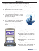
ARGO USER MANUAL 2. Insert the cleaning card into the card reader and move in and out several times. 3. Remove the cleaning card and turn over to use other side. 4. Insert again several times. 5. Remove cleaning card and discard. They are designed to be used only once.
SECTION 5: SETUP BASICS 12.
ARGO USER MANUAL INTRODUCTION Triton ATMs require a minimum amount of configuration in order to place them into fully functional order. These configuration requirements are listed in the steps below. These are the minimum requirements for bringing the ATM live and in service. Please refer to the XScale/X2 Configuration Manual for other, optional configuration assistance. LOGON Once the ATM is powered on, to logon to the system’s Management Functions screen: 1.
ARGO USER MANUAL CHANGE MASTER PASSWORD (Resolves Error Code 246.) To change the master password, starting from the Main Menu: 1. Press 4 (Password Maintenance). 3. Enter the new password on the popup screen. Enter password only, not the “00” user ID of the Master. 2. The password may consist of between 4-12 numeric digits. Press 1 (Change User Password). 41 4. Press Enter. 5. Repeat steps 3 and 4 to confirm new password.
ARGO USER MANUAL SET DENOMINATION (Resolves error code 186.) Denomination for each cassette must be set up. The process depends on what type dispenser is in the ATM. 1. From the Main Menu, press 6 (Terminal Configuration). Denomination setup steps from this point are determined by dispenser: 4. A) MiniMech, SDD, SCDU, or HCDU B) TDM250 C) NMD50 4. A) MiniMech, SDD, SCDU or HCDU 1) Press 7 (Multiple Amount). 2. Press 4 (Cassette Setup).
ARGO USER MANUAL 4. A) MiniMech, SDD, SCDU, or HCDU (continued) 2) Press 7 (Multiple Amount). 3) Follow replenishing cash steps (see Section 3), then replace cassette and press Enter. 4) Enter the denomination amount. 3) At prompt, remove selected cassette from the dispenser, then press Enter. 5) Press Enter. 4) Follow replenishing cash steps (see Seciton 3), then replace cassette and press Enter. 6) For HCDU with two cassettes, repeat these steps for the second cassette.
ARGO USER MANUAL the cassette being set up appears. 4. B) TDM250 (continued) 3) Press 7 (Multiple Amount). 7) Press 6 (Cassette in Service) to place cassette in service (checkmark displays). 4) At prompt, remove selected cassette from the dispenser, then press Enter. 8) Repeat these steps for the other TDM cassette in the dispenser. C) NMD50 1) Press 2 (All Cassettes Locked) to uncheck (unlock). 5) Follow replenishing cash steps (see Seciton 3), then replace cassette and press Enter.
ARGO USER MANUAL 4. C) NMD50 (continued) 9) Press 2 (All Cassettes Locked) to check (lock) both cassettes. 7) Press 6 (Cassette in Service) to place cassette in service (checkmark displays). 8) Repeat steps 2-7 for the other NMD cassette in the dispenser. ENTER HOST PHONE NUMBER (Resolves error code 185.) The default communication protocol is dialup (TDL) as shown here. For other types of communication with the host processor, see the XScale/X2 Configuration Manual or contact Technical Support.
ARGO USER MANUAL Enter Host Phone Number (continued) 3. On the Communications menu, press 1 (Primary Phone Number). TDL (Triton Dynamic Language) is the default setting for Communications Protocol and is the dialup protocol. Changing this setting may change the options available on this screen. 4. Enter the host phone number to dial for transactions. If setting the Communication Protocol to TCP/IP, the options on the menu change. The differences are circled below.
ARGO USER MANUAL ENTER TERMINAL ID (Resolves error code 189.) The terminal ID is provided by the host processor. 1. From the Main Menu, press 6 (Terminal Configuration). 4. Enter the Terminal ID received from the Host Processor. When entering alpha characters, use the virtual keyboard. NOTE: Ensure there is NO space before the terminal ID. 2. 3. On the Terminal Configuration menu, press 1 (General Parameters).
ARGO USER MANUAL ENTER MASTER KEYS (Resolves error code 190.) The following steps are for entry of the DES PIN Master Keys. Master Keys and information regarding them are provided by the Host Processor. 1. On the Main Menu, press 7 (Key Management). 3. A) T7 PCI EPP a) On Key Management menu, press 4 (Set Passwords). 2. On initial setup, the system requires secure passwords to be changed for Master Keys. Press ENTER at the prompt.
ARGO USER MANUAL 3. A) T7 PCI EPP (continued) f) Re-enter new password to confirm, and press ENTER. c) Enter default password (000000) for User 2, and press ENTER. g) Press 2 (Change User 2 Password) and repeat steps e) and f) for User 2. d) Press 1 (Change User 1 Password). e) Enter new password for User 1, and press ENTER. NOTE: The password must be between 6-14 numeric digits. NOTE: Some hosts may provide the passwords for User 1 and User 2.
ARGO USER MANUAL B) T5 PCI EPP c) Enter password for the user, and press ENTER. a) On Key Management menu, press 4 (Set Passwords). NOTE: On the T5 EPP, the password must be between 8-16 numeric digits. NOTE: Some hosts may provide the passwords for User 1 and User 2. d) Re-enter the password for the user to confirm, and press ENTER. Until passwords are set, all other options on this menu except Update EPP Firmware are inactive. b) Press 1 (Set User 1 Password).
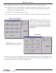
ARGO USER MANUAL 4. On the Key Management screen, press 1 (Enter Master Keys). 5. Enter User 1 password, and press ENTER. 6. Enter User 2 password, and press ENTER. 8. Press ENTER to select the default setting of New Key. 9. Enter PIN Master Key part A using the function keys and keypad schema shown on screen. 10. Press F7 (Enter) when all of the Master Key part is entered. 11. Verify the check digits match those provided by the Host Processor for this part of the Master 7.
ARGO USER MANUAL 12. Press ENTER when prompted to add part to existing key. 14. Press ENTER when successful. 15. Press CANCEL and proceed to Download Working Keys. 13. Repeat steps 9-12 for part B of the Master Key. DOWNLOAD WORKING KEYS (Resolves error code 188.) 1. On the Key Management menu, press 2 (Download Working Keys). The terminal proceeds to contact the host. 3. 2. Press ENTER to continue. 52 Press ENTER once the download is complete.
ARGO USER MANUAL Once these steps are completed and the terminal is in communication with the host, the ATM comes into service. It is now ready to process transactions. There are several other, optional configuration features, but these complete the basic setup requirements. For further information, see the XScale/X2 Configuration Manual or contact Triton Technical Support: North America: 1 (800) 259-6672 Outside of North America: +1 (228) 575-3100 12.
APPENDIX A SOFTWARE LICENSE AGREEMENT COMPLIANCE / EMISSION STATEMENTS A-1
APPENDIX A AUTOMATED TELLER MACHINE (“ATM”) SOFTWARE END-USER AGREEMENT IMPORTANT: PLEASE READ CAREFULLY: BY INSTALLING OR OTHERWISE USING THE ATM, YOU (AS THE OWNER OR LESSEE OF THE ATM). AGREE TO BE BOUND BY THE FOLLOWING TERMS AND CONDITIONS, INCLUDING, WITHOUT LIMITATION, THE WARRANTY DISCLAIMERS, LIMITATIONS OF LIABILITY AND TERMINATION PROVISION WHICH APPLY TO YOUR USE OF THE ATM SOFTWARE CONTAINED IN THIS ATM AND IS HEREBY LICENSED BY TRITON SYSTEMS OF DELAWARE, LLC.
SOFTWARE LICENSE AGREEMENT / COMPLIANCE/EMISSION STATEMENTS DISCLAIMER OF WARRANTIES AND LIMITATION OF DAMAGES TO THE EXTENT PERMITTED BY LAW, THIS ATM SOFTWARE, INCLUDING ALL INCORPORATED THIRD PARTY SOFTWARE, AND DERIVATIVES IS PROVIDED, “AS IS”. TRITON MAKES NO REPRESENTATIONS WITH RESPECT TO, AND DOES NOT WARRANT THE PERFORMANCE OR RESULTS YOU OR YOUR CUSTOMERS MAY OBTAIN BY USING THE ATM.
APPENDIX A COMPLIANCE / EMISSION STATEMENTS DISCLAIMER The manufacturer of the Automated Teller Machine (ATM) product(s) described herein makes no representations or warranties, either expressed or implied, by or with respect to anything in this manual, and shall not be liable for any implied warranties of fitness for a particular purpose or for any indirect, special, or consequential damages.
APPENDIX B WARRANTY SERVICE STATEMENT B-1
APPENDIX B WARRANTY STATEMENT Manufacturer warrants that the Products delivered to Distributor will perform in accordance with the Manufacturer’s published specifications, and as outlined in the Manufacturer’s booklet entitled “Thirteen Months Parts Only Limited Warranty” for thirteen months from date of shipment in Long Beach, MS. Distributor acknowledges that it has received a copy of such booklet, that it has read its entirety and that it understands and agrees with its contents.
WARRANTY STATEMENT DEFENSE OF INFRINGEMENT CLAIMS If notified promptly in writing of any action (and all prior claims relating to such action) brought against the Distributor based on a claim that Distributor’s use of the goods infringes a patent or other intellectual property right, and if given access by Distributor to any information distributor has regarding such alleged infringement, Manufacturer agrees to defend Distributor in such action at its expense and will pay any costs or damages finally award
APPENDIX B INTERPRETATION AND OTHER PAROLE EVIDENCE This writing is intended by the parties as final expression of their agreement and is intended also as a complete and exclusive statement of the terms of their agreement. No course of prior dealing between the parties and no usage of the trade shall be relevant to supplement or explain any term used in these terms and conditions.
WARRANTY STATEMENT Limited Warranty covers normal use.
APPENDIX B Should you specify the carrier, we recommend that you explore with this chosen carrier the policies and procedures regarding shipping damage claims prior to selecting them as your preferred carrier. If the equipment receives structural damage and is in an un-installable condition, Triton will work with you to arrange for a replacement unit to be shipped as soon as possible. The purchaser will be billed for the replacement unit.
WARRANTY STATEMENT CALLS FOR SERVICE OR REPAIR Calls for service or repair will be accepted from authorized service technicians only. End users must contact either the sales organization that placed the equipment or an authorized third party service organization to obtain service. The sections that follow describe the policies and procedures that relate to the repair and replacement of malfunctioning equipment.
APPENDIX B THIS PAGE INTENTIONALLY LEFT BLANK B-8
APPENDIX C ELECTRONIC LOCKS AND BATTERY STRAIGHT DEAD BOLT SWING BOLT
APPENDIX C ** IMPORTANT ** Read this page BEFORE proceeding. New imperative information. Super Master Reset Password BOTH types of electronic locks are now set with a Super Master Reset Password. The Super Master Reset Password should only be used if the Manager Password has been lost/forgotten.
ELECTRONIC LOCKS AND BATTERY Entering the Combination - Both Styles The electronic lock combination(s) consists of six digits. Upon arrival, the combination(s) of the lock should already be set at 1-2-3-4-5-6. After installation of the unit has been completed: 1. Enter the preset combination and check for proper operation. After each keypress, the lock will beep. After the final digit has been entered, the lock will beep twice and the open period will begin. 2.
APPENDIX C Programmable Features The locks are initially set with the standard feature of a single 6-digit code. Based on your requirements, additional features may be added in the lock BUT THEY MUST BE PRE-PROGRAMMED by Triton prior to shipment of the unit. - Manager (Factory set to 1-2-3-4-5-6): Add/remove second user Enable/disable second user - Dual Code: Two (2) combinations required to open.
ELECTRONIC LOCKS AND BATTERY Reinstate User (Manager feature only) 1. 2. 3. Always perform this operation with the door open Enter Manager Code and HOLD DOWN LAST DIGIT OF CODE until the lock signals with two (2) sets of double beeps. PRESS 1. Lock signals once. User is now reinstated. If a mistake is made, wait thirty (30) seconds and repeat steps 1 - 2. Remove User (Manager feature only) Always perform this operation with the door open 1.
APPENDIX C Battery Maintenance Battery Low Warning Repeated beeping during an opening indicates that the battery is low and needs to be replaced. Triton recommends replacement of the battery at least twice annually. The battery box is located on the inside of the door. Note: If the lock will not operate (i.e. repeated beeping or no beeping) while the door is closed and locked, the battery must be energized from the two external terminals on the front of the push-button panel.
APPENDIX D MECHANICAL LOCKS
APPENDIX D Entering the Combination There are two marks on the dial ring (Refer to Figure 1). The index at the top is used for opening the lock. The index 30 degrees to the left is used only when changing the combination. The dial should always be turned slowly and evenly. A revolution is counted each time the selected number is aligned with the opening index. DO NOT TURN THE DIAL BACK TO COMPENSATE FOR OVER DIALING A NUMBER.
APPENDIX G T9 KEYPAD COPYRIGHT NOTICE © 2014 Triton. All Rights Reserved.
APPENDIX G Document Updates May 14, 2014 Original ** WARNING ** Once the T9 EPP Keypad is installed and activated in the unit, it CANNOT be removed. If the keypad is removed from the unit after activation, reactivation is required and can only be performed by Triton Technical Support. The T9 EPP Keypad is mostly identical to the T5 EPP Keypad except for: • The T9 EPP contains a removal detection switch that deactivates / TAMPERS the EPP if the EPP is ever removed from the ATM.
T9 KEYPAD New Error Codes to Support the T9 EPP • Error Code 625: SPED - Not Activated Cause: The EPP has not yet been activated for use. Recommended Action: Activate the EPP. • Error Code 626: SPED - Not Authorized Cause: The EPP has been removed from the ATM. Recommended Action: Call Triton Technical Support for activation code.
APPENDIX G To Install the T9 Keypad The T9 EPP Keypad is a drop in replacement for new units manufactured with a T5 or T7 EPP Keypad. No additional parts are required. • All RL1613, Traverse and ARGO were manufacturered with a T5 or T7 EPP. (See NOTE below) • All X2 RL23XX, RL53XX and RT23XX were manufactured with a T5 or T7 EPP beginning January 2, 2008 (Julian date of 08002).
T9 KEYPAD Prior to T9 Keypad Activation The Device Status report will indicate if the EPP has been installed correctly into the unit. This is imperative to check prior to activation as if it is not installed correctly, the EPP activation will fail. 1. Log into Management Functions. 2. If Favorites page appears, press 0 - Main Menu. Press 2 - Diagnostics. 3. Press 8 - Keypad. 4. Press 1 - Device Status. 5. If the T9 EPP Keypad has been installed correctly, the “Remove Detector Activated:” will read “TRUE”.
APPENDIX G To Activate the T9 Keypad NOTE: Activation is NOT required for units that ship with the T9 EPP installed. 1. Log into Management Functions. 2. If Favorites page appears, press 0 - Main Menu. Press 2 - Diagnostics. 3. Press 8 - Keypad. 4. Press 4 - Activate EPP. 5. When the activation is successful, the “EPP activation successful” message will appear.
T9 KEYPAD To Reactivate the T9 Keypad NOTE: Triton Technical Support CANNOT supply an activation code without the Operator Id, Serial Number and Nonce numbers supplied in Step 5. 1. Log into Management Functions. 2. If Favorites page appears, press 0 - Main Menu. Press 2 - Diagnostics. 3. Press 8 - Keypad. 4. Press 4 - Activate EPP. 5. The following screen will appear. An activation code is required from Triton Technical Support to reactivate the T9 EPP Keypad.
APPENDIX G Replacing the battery in the T9 Keypad NOTE: Do NOT remove the battery from the T9 EPP without FIRST connecting a new battery!! This EPP will be permanently damaged if the battery is removed and the keypad is unpowered before connecting a new battery. 1. Shutdown the unit with the proper shutdown procedures. Turn the power switch on the power supply to the OFF (O) position. 2. Remove the battery cover from the EPP. Set the cover aside for reinstallation. 3.
SUPPLEMENT A T5 AND T7 PCI-EPP BATTERY REPLACEMENT PROCEDURES SA-1
T5 PCI-EPP BATTERY REPLACEMENT ** CAUTION ** You must not remove battery from EPP without FIRST connecting a new battery! This EPP will be permanently damaged if unpowered and battery is removed before connecting a new battery! Battery Case Spare battery connection EXISTING BATTERY - DO NOT REMOVE BEFORE CONNECTING A SPARE BATTERY FIRST! The spare battery for the T5 PCI-EPP may be purchased from Triton Systems: P/N 01300-00025 (T5 PCI-EPP Lithium Backup Battery) SA-2
SUPPLEMENT A - T5 / T7 PCI-EPP BATTERY REPLACEMENT PROCEDURES T7 PCI-EPP BATTERY REPLACEMENT * IMPORTANT* You may remove the battery without risk of damage to the EPP. You have approximately 2-5 minutes to replace with a spare battery before losing the data stored (keys, passwords) in the keypad.
THIS PAGE INTENTIONALLY LEFT BLANK SA-4
T5 PCI-EPP SUPPLEMENT B KEY MANAGEMENT PROCEDURES T7 PCI-EPP
T5 - T7 PCI-EPP (T5) / KEY MANAGEMENT PROCEDURES DIFFERENCES WITH THE T5 PCI-EPP KEYPAD YOU MUST NOT REMOVE BATTERY FROM EPP WITHOUT FIRST CONNECTING A NEW BATTERY! THIS T5 EPP WILL BE PERMANENTLY DAMAGED IF UNPOWERED AND BATTERY IS REMOVED BEFORE CONNECTING A NEW BATTERY! USER PASSWORDS MUST BE AT LEAST 8 CHARACTERS, RATHER THAN 6. EPP WILL PROMPT WITH ERROR IF FEWER CHARACTERS ENTERED AND THEN TAKE YOU BACK TO PASSWORD ENTRY AT POINT YOU LEFT OFF. THERE IS NO WAY TO CLEAR THE PASSWORD.
SUPPLEMENT B - KEY MANAGEMENT PROCEDURES KEY MANAGEMENT PROCEDURES (W/T5 PCI-EPP INSTALLED) E NTER M ANAGEMENT FUNCTIONS > MAIN MENU > KEY MANAGEMENT. NOTE: PREVIOUSLY, US- ERS HAD TO ENTER THE INITIAL PASSWORD OF SIX (6) “ZEROS” BEFORE BEING ALLOWED TO SET THE PASSWORDS. THIS IS NO LONGER REQUIRED (FOR T5 PCI-EPP ONLY). THE “SET PASSWORD INI- S ELECT “S ET U SER 1 P ASSWORD ” OPTION . E NTER NEW PASSWORD FOR U SER 1. PASSWORDS CAN BE ANYWHERE FROM ‘8’ TO ‘16’ DECIMAL DIGITS.
T5 - T7 NEXT, SELECT “SET USER S ELECT “E NTER PIN 2 PASSWORD” OPTION. FOLLOW MASTER KEY” OPTION. THE SAME PROCEDURE FOR ENTERING A NEW PASSWORD FOR USER 2. W HEN COMPLETED , THE “S ET USER 2 PASSWORD” OPTION WILL CHANGE TO “C HANGE U SER 2 PASSWORD”. AFTER COMPLETION, HIT TO ENTER MASTER KEYS SCREEN (STEP 5). SELECT “ENTER MASTER KEYS” OPTION. IMPORTANT: THE REST OF THE PROCEDURES MUST BE COMPLETED WITHIN A 10 MINUTE PERIOD.
SUPPLEMENT B - KEY MANAGEMENT PROCEDURES USER 2 ENTERS THE SECOND KEY PART (32 CHARACTERS). REFER TO STEP 8 FOR ENTERING KEYS. F5 F7 T HE “C HECK PROMPT APPEARS. PRESS . A DIGITS ” PROMPT APPEARS TO ENTER THE SECOND KEY PART. T HE “C HECK PROMPT APPEARS. 11 DIGITS ” YOU WILL BE PROMPTED THAT THE KEY WAS SUCCESSFULLY CHANGED. PRESS . REPEAT SEQUENCE FOR ENTERING MAC M ASTER KEY , IF REQUIRED.
T5 - T7 KEY MANAGEMENT PROCEDURES (W/T7 PCI-EPP INSTALLED) E NTER M ANAGEMENT FUNCTIONS > MAIN MENU > KEY MANAGEMENT. THE T7 USER PASSWORDS ARE INITIALLY SET TO SIX (6) “ZEROS (SIMILAR TO VEPP) BEFORE BEING ALLOWED TO SET THE PASSWORDS. S ELECT “S ET U SER 1 P ASSWORD ” OPTION . E NTER NEW PASSWORD FOR U SER 1. PASSWORDS CAN BE ANYWHERE FROM ‘6’ TO ‘14’ DECIMAL DIGITS. PRESS . YOU WILL BE PROMPTED AGAIN TO CONFIRM THE NEW PASSWORD. THE “SET PASSWORD INI- RE-ENTER NEW PASSWORD.
SUPPLEMENT B - KEY MANAGEMENT PROCEDURES NEXT, SELECT “SET USER ENTER USER 1 PASSWORD. 2 PASSWORD” OPTION. FOLLOW PRESS . THE SAME PROCEDURE FOR ENTERENTER USER 2 PASSWORD. ING A NEW PASSWORD FOR USER PRESS . 2. W HEN COMPLETED , THE “S ET USER 2 PASSWORD” OPTION WILL CHANGE TO “C HANGE U SER 2 PASSWORD”. AFTER COMPLETION, HIT TO ENTER MASTER KEYS SCREEN (STEP 5). S ELECT “E NTER PIN MASTER KEY” OPTION. SELECT “ENTER MASTER KEYS” OPTION.
T5 - T7 11 USER 2 ENTERS THE SECOND KEY PART (32 CHARACTERS). KEY R EFERENCE THE KEY LAYOUT REFER TO STEP 9 FOR ENTERING DISPLAY BELOW. THE MAIN KEY- KEYS. PAD WILL MIRROR THE NUMBER/ ALPHANUMERIC KEYS. USER 1 ENTERS THE FIRST PART (32 CHARACTERS ). AFTER ENTERING THE KEYS, PRESS THE OPTION ON THE RIGHT - SIDE FUNCTION KEY . 12 THE “CHECK DIGITS” PROMPT APPEARS. T HE “C HECK D IGITS ” PROMPT APPEARS. PRESS . YOU WILL BE PROMPTED THAT THE KEY WAS SUCCESSFULLY CHANGED.