MODEL 8100 AUTOMATED TELLER MACHINE USER / INSTALLATION MANUAL VERSION 1.0 TDN 07100-00055 12/2005 CORPORATE HEADQUARTERS: 522 E. Railroad Street Long Beach, MS 39560 Phone: (228) 868-1317 Fax: (228) 868-0437 RMA (RETURN MATERIAL AUTHORIZATION) RETURN ADDRESS: 21405 Avenue “B” Long Beach, MS 39560 COPYRIGHT NOTICE © 2005 Delaware Capital Formation, Inc. All Rights Reserved.
MODEL 8100 USER / INSTALLATION MANUAL DISCLAIMER The manufacturer of the Automated Teller Machine (ATM) product(s) described herein makes no representations or warranties, either expressed or implied, by or with respect to anything in this manual, and shall not be liable for any implied warranties of fitness for a particular purpose or for any indirect, special, or consequential damages.
MODEL 8100 USER / INSTALLATION MANUAL Harm to the Network: If the Model 8100 ATM causes harm to the telephone network, the telephone company will notify the customer that a temporary discontinuous of service may be required. If advanced notice is not possible, the telephone company will notify the customer as soon as possible. You will be advised of your right to file a complaint with the FCC if you believe it’s necessary.
MODEL 8100 USER / INSTALLATION MANUAL Before installing this equipment, users should ensure that it is permissible to be connected to the facilities of the local telecommunications company. The equipment must also be installed using an acceptable method of connection. The customer should be aware that compliance with the above conditions may not prevent degradation of service in some situations. Repairs to certified equipment should be coordinated by a representative designated by the supplier.
MODEL 8100 USER / INSTALLATION MANUAL Les réparations de matériel homologué doivent être coordonnées par un représentant désigné par le fournisseur. L’entreprise de télécommunications peut demander à I’utilisateur de débrancher un appareil à la suite de réparations ou de modifications effectuées par l’utilisateur ou à cause de mauvais fonctionnement.
MODEL 8100 USER / INSTALLATION MANUAL NOTE: This equipment has been tested and found to comply with the limits for a Class A digital device, pursuant to Part 15 of FCC rules. These limits are designed to provide reasonable protection against harmful interference when the equipment is operated in a commercial environment.
MODEL 8100 USER / INSTALLATION MANUAL NOTICES Copyright © Delaware Capital Formation, Inc., 2005. ALL RIGHTS RESERVED This publication is protected by copyright and all rights are reserved. No part of it may be reproduced or transmitted by any means or in any form, without prior consent in writing from Triton Systems of Delaware, Inc. The information in this publication has been carefully checked and is believed to be accurate. However, Triton Systems of Delaware, Inc.
MODEL 8100 USER / INSTALLATION MANUAL WARRANTY STATEMENT Manufacturer warrants that the products delivered to a distributor will perform in accordance with the Manufacturer’s published specifications for thirteen months from date of shipment in Long Beach, MS. Manufacturer’s warranty shall not apply to any damage resulting from abuse, negligence, accident, or to any loss or damage to the products while in transit.
MODEL 8100 USER / INSTALLATION MANUAL the defense of any such action and all negotiations for its settlement or compromise.
MODEL 8100 USER / INSTALLATION MANUAL WAIVER INEFFECTIVE No claim or right arising out of or relating to a breach of these terms and conditions can be discharged in whole or in part by a waiver or renunciation of the claim or right unless the waiver or renunciation is supported by consideration and is in writing signed by the aggrieved party.
MODEL 8100 USER / INSTALLATION MANUAL LIMITED WARRANTY COVERS NORMAL USE.
MODEL 8100 USER / INSTALLATION MANUAL • If possible, call the shipping company before the driver leaves your delivery site. Make note of the damage on the “receipt of delivery’ paperwork. If this is not possible, call them as soon as possible to report the damage. • Take photographs of the damaged packaging prior to opening the boxes. If this is not possible, make note of key points, such as whether the equipment is on a pallet, if the banding is intact, how the boxes are damaged, etc.
MODEL 8100 USER / INSTALLATION MANUAL TRITON’S TECHNICAL SERVICES DEPARTMENT The primary purpose of the Technical Services Department is to provide assistance to customers in the operation, trouble shooting, and repair of equipment manufactured by Triton. A toll-free phone number (1-800-259-6672) is provided for convenience. The Technical Services department operates to serve our customers. The staff is trained to follow our policies and procedures to ensure fair and uniform treatment of all our customers.
MODEL 8100 USER / INSTALLATION MANUAL QUESTIONS ON OPERATION OF EQUIPMENT Technical support is available to owners of Triton equipment and to qualified service personnel. When calling for help with the configuration or operation of a Triton product, the caller must provide either positive identification as a service technician or the serial number of a Triton terminal. Technical support is provided during normal business hours for the life of the product.
MODEL 8100 USER / INSTALLATION MANUAL Contents SECTION 1 - INTRODUCTION ........................................................ 1 WHAT’S IN THIS MANUAL ................................................................................ 2 FEATURE HIGHLIGHTS ....................................................................................... 3 STANDARD FEATURES ....................................................................................... 4-5 SECTION 2 - BASIC OPERATION ...........................
MODEL 8100 USER / INSTALLATION MANUAL Contents CONFIGURE TERMINAL ................................................................................... 49 TCP/IP CONFIGURATION ............................................................................... 49 NETWORK SETTINGS ......................................................................................... 50-51 TEST TCP/IP ...................................................................................................
MODEL 8100 USER / INSTALLATION MANUAL Contents SECTION 6 - TDM ERROR CODES / CLICK COUNTS .................... 83 TDM ERROR CODES ............................................................................................ 84-85 TDM HARDWARE STATUS CODES ...................................................................... 86 TDM CLICK COUNTERS ....................................................................................... 87-93 APPENDIX A - INSTALLATION PROCEDURES ...............................
MODEL 9100 USER / INSTALLATION MANUAL THIS PAGE INTENTIONALLY LEFT BLANK xviii
SECTION 1 INTRODUCTION 1
MODEL 8100 USER / INSTALLATION MANUAL WHAT’S IN THIS MANUAL This User / Installation manual describes the operating features of the Model 8100 series ATM and shows how to perform the procedures that would typically be performed by the owner or operator personnel. It also includes installation procedures for the terminal. The user manual is divided into the following sections: Section 1, Introduction. Summarizes the basic features of the Model 8100 series ATM. Section 2, Basic Operation.
INTRODUCTION FEATURE HIGHLIGHTS Important features of the 8100 series ATM are highlighted in the following list: ! Modular architecture eases troubleshooting and servicing. ! Supports dial-up, wireless, and Ethernet (TCP/IP) communications. ! Single cassette design using a TDM-50 (new) dispensing mechanism. ! 5.7" (145 mm) monochrome or color LCD display. ! 14.4 baud modem standard (33.6 baud optional). ! Satisfies Americans with Disabilities Act (ADA) specifications for height and access. Audio compliant.
MODEL 8100 USER / INSTALLATION MANUAL STANDARD FEATURES ! Management Functions. Enable extensive control and customization of the ATM’s operating parameters. ! EPROM Functions. The EPROM function provides low-level diagnostic and software update operations. ! Password Protection. Access to Management functions and EPROM areas is protected with passwords. ! MAC Encryption Support. Message Authentication Code (MAC) data encryption protocol.
INTRODUCTION ! Coupons. Coupons are printed by the receipt printer and prizes awarded to customers based on random and/or withdrawal amount-based transactions. Coupon text can be entered locally or downloaded using Triton Connect software. ! Status Monitoring. The ATM can periodically transfer status information to the host processor.
MODEL 8100 USER / INSTALLATION MANUAL THIS PAGE INTENTIONALLY LEFT BLANK 6
SECTION 2 BASIC OPERATION 7
MODEL 8100 USER / INSTALLATION MANUAL INTRODUCTION This section describes the basic operation of the terminal. The following topics are covered: 1. CONTROL PANEL LAYOUT. Describes the layout of the terminal’s control panel. 2. KEYPAD OPERATION. Describes the use of the alphanumeric keypads. 3. MENU-BASED OPERATION. Gives a general overview of the terminal display interface. 4. ACCESSING M ANAGEMENT FUNCTIONS .
BASIC OPERATION CONTROL PANEL LAYOUT The user interface of the terminal consists of the LCD screen, receipt chute, card reader, speaker, headphone jack (visually impaired), and 24 keys on three keypads. The Function keys are arranged in two four-key groups, one group on either side of the LCD display. The main keypad consists of 10 alphanumeric keys, two arrow keys and four large control keys, all located in a 16-key group beneath the LCD screen.
MODEL 8100 USER / INSTALLATION MANUAL FUNCTION KEYPADS The primary menu navigation keys, called Function keys, are arranged in two four-key groups, one group on either side of the LCD screen. A Function key is only active when a function or menu option name is displayed (if the display is “grayed out”, that option is not available). The Function keys are designated F1 through F8, as shown in Figure 2-2. F1 F2 F3 F4 F5 F6 F7 F8 CTRL Figure 2-2. Function keys.
BASIC OPERATION Each of the numbered keys (<0> through <9>) has six characters available. See Table 2-1, Keypad characters. On most of these keys (<2> through <9>), the first three of the available characters are alphabetic, and are printed on the keycap above the number character. Two keys, the <0> and <1>, are different. The <0> key does not show any additional characters, while the <1> key shows two alphabetic characters (‘QZ’).
MODEL 8100 USER / INSTALLATION MANUAL MENU-BASED OPERATION The terminal operates as a menu driven system. Messages and menu options presented on the LCD display screen guide the user’s actions. The desired menu option is selected by pressing one of the keys located to the left and right of the display. For the purpose of security many screens timeout after a preset time interval, usually 30 seconds. The timeout length may vary depending on the function being performed.
BASIC OPERATION CUSTOMER TRANSACTIONS A customer begins a transaction by selecting a service from the Customer screen options. ( PaySpot™, CashWorks™, Western Union® or ATM- Get Cash Now) They insert their ATM card into the card reader of the terminal. The card must be inserted so that the magnetic stripe can be scanned by the card reader’s sensor. If the customer inserts the card incorrectly, a warning message will be displayed, accompanied by several beeps to get their attention.
MODEL 8100 USER / INSTALLATION MANUAL The ATM sends the customer transaction request to a processor. A processor is a financial intermediary, such as an Independent Sales Organization (ISO), bank, or other financial institution that provides transaction-processing services for ATMs. The ATM must be set up with a particular processor before customer transactions can take place. The processor routes the transaction to the appropriate ATM network.
BASIC OPERATION VOICE-ENABLED TRANSACTIONS The terminal provides voice feedback via an integrated output jack, enabling sight-impaired users to plug in a set of headphones and receive spoken instructions to assist them in using the ATM (Figure 2-4). A raised symbol helps a user locate the headphone jack. The ATM will automatically detect when a headphone has been plugged into the jack, and will immediately switch into voice mode.
MODEL 8100 USER / INSTALLATION MANUAL THIS PAGE INTENTIONALLY LEFT BLANK 16
SECTION 3 MANAGEMENT FUNCTIONS 17
MODEL 8100 USER / INSTALLATION MANUAL INTRODUCTION This section describes the Management Functions available with the ‘MASTER’ password for accessing the ATM. When the Customer Welcome screen is displayed, you can access the Management Functions menu by following the procedure described next. ACCESSING THE MANAGEMENT FUNCTIONS MENU 1. Press and hold down the key; while holding down the key, press the <1> key. Release both keys. After a moment the top menu will be displayed. 2.
MANAGEMENT FUNCTIONS Figure 3-1. Main menu screen. NEW OR MODIFIED MANAGEMENT FUNCTIONS The majority of the Management Functions are configured the same as before but they may have been relocated in the menu structure. A brief synopsis of each function is provided. A summary of the changes to the Management Functions is provided below: " MAIN MENU - Three (3) major configuration paths now exist: Terminal, Services, and Processors.
MODEL 8100 USER / INSTALLATION MANUAL MAIN MENU ACCESS INSTRUCTIONS: 1. Access Management Functions by entering your password. The MAIN MENU screen will be displayed. DESCRIPTION: The Main Menu screen allows the service provider/terminal operator to access the following Management functions: 1. Configure Terminal. Used to configure operating parameters for the ATM terminal. 2. Configure Services. Used to select transaction types, account types, and surcharging setup. 3. Configure Processors.
MANAGEMENT FUNCTIONS CONFIGURE TERMINAL ACCESS INSTRUCTIONS: 1. From the MAIN MENU screen, select CONFIGURE TERMINAL. DESCRIPTION: The following options will be available from the CONFIGURE TERMINAL screen: 1. Cassette Setup. Allows the terminal operator to view and change cassette parameters. 2. Date/Time Functions. Provides a menu related to configuration of date and time parameters 3. Language Idioma.
MODEL 8100 USER / INSTALLATION MANUAL CONFIGURE TERMINAL (M ORE ) 1. AD Screens. This feature enables or disables the display on an idle terminal to alternate between the Welcome Screen and a screen containing graphics and text elements used to make an advertisement screen. 2. Random/Level Prize Coupons. Provides access to setup terminal operations for issuing printed and dispensed prize coupons. 3. Change Messages. Allows information for various terminal and receipt messages to be changed or authored.
MANAGEMENT FUNCTIONS CASSETTE SETUP ACCESS INSTRUCTIONS: 1. From the MAIN MENU screen, select CONFIGURE TERMINAL. 2. From the CONFIGURE TERMINAL screen, select CASSETTE SETUP. DESCRIPTION: The following options will be available from the CASSETTE SETUP screen: 1. Relearn Bill Thickness. Enables you to force the dispenser to enter the learning mode. 2. International Currency. Allows operator to select one of eleven (11) possible monetary symbols that describe the type of currency being used. 3.
MODEL 8100 USER / INSTALLATION MANUAL CASSETTE PARAMETERS ACCESS INSTRUCTIONS: 1. From the CONFIGURE TERMINAL screen, select CASSETTE SETUP. 2. From the C ASSETTE S ETUP screen, select CASSETTE PARAMETERS. 3. Select CASSETTE “A”, “B”, OR “C” (cassette “D” will be grayed out). DESCRIPTION: The following options will be available from the CASSETTE SETUP screen: 1. Set Bill Dimensions. Note: Does not apply for TDM dispensers. 2. Value.
MANAGEMENT FUNCTIONS CONFIGURE PROCESSORS ACCESS INSTRUCTIONS: 1. From the MAIN MENU screen, select CONFIGURE PROCESSORS. 2. From the CONFIGURE PROCESSORS screen, select option (1), (2), (3), or (4). ** Important** Option (1) MUST be configured. It is the default processor for standard ATM transactions. DESCRIPTION: The following options will be available from the C ONFIGURE P ROCESSORS screen: 0. Processor Name. Allows entry for the name of the specified processor (Ex: CALYPSO) 1. Terminal ID.
MODEL 8100 USER / INSTALLATION MANUAL CONFIGURE PROCESSORS The remaining options are toggled to either Enable or Disable that particular function. 5. 6. # # # # 7. Send Terminal Totals. When this option is Enabled, the terminal will send accumulated totals information to the processor during the close operation. Option 1. Terminal ID Status Monitoring. Status monitoring is a feature available with selected processor software.
MANAGEMENT FUNCTIONS CONFIGURE PROCESSORS 8. Communications Header. This optional feature is only applicable to certain processors. When required, it must be Enabled and have the correct data in the header data field. The Communication Header consists of alphanumeric characters. **Warning** Enabling the COMMUNICATION HEADER when using a processor that doesn’t use this feature will prevent any type of transaction from completing.
MODEL 8100 USER / INSTALLATION MANUAL KEY MANAGEMENT ACCESS INSTRUCTIONS: 1. From the MAIN MENU screen, select CONFIGURE PROCESSORS. 2. From the CONFIGURE PROCESSORS screen, select option (2) for KEY MANAGEMENT. DESCRIPTION: The KEY MANAGEMENT function provides access to the ATMs functions that control the method of entry for MAC Master Keys and/or PIN Master Keys, downloading the PIN Working Keys, and displaying the Check Digits. The new VEPP requires that two key parts for each key are loaded.
MANAGEMENT FUNCTIONS 2. Password Required - When “Enter Master Keys” is selected, you will be prompted to enter two (2) passwords. If this is an initial setup, the default password is six (6) zeros (000000) for each. You will then be prompted to change passwords. Passwords MUST be changed! 3. Change Password (Initial Setup) The VEPP requires that no default password can be entered. If a user enters the default password, the VEPP will force the user to change them before they can enter keys. 4.
MODEL 8100 USER / INSTALLATION MANUAL 6. Enter Master Keys - This screen allows selection to enter the Master keys. You MUST enter PIN Master keys. DO NOT enter keys in the MAC Master keys unless processor directs. You MUST enter two (2) sets of keys (32 alpha/ numerical). 7. Enter Keys - Enter the first (32) alpha/numerical key. The on-screen keypad legend describes the ATMs keypad for entering numbers and characters. Select “ENTER” using the display function key. 8.
MANAGEMENT FUNCTIONS CONFIGURE SERVICES ACCESS INSTRUCTIONS: 1. From the MAIN MENU screen, select CONFIGURE SERVICES. DESCRIPTION: The following options will be available from the Configure Services screen: *Note* Any service-specific functions (PaySpot, CashWorks, Western Union) must have a processor selected for their specific service, if used. STD ATM Configuration uses the default processor number one (1). You MUST configure processor number (1) for standard terminal operations. 1.
MODEL 8100 USER / INSTALLATION MANUAL STD ATM CONFIGURATION ACCESS INSTRUCTIONS: 1. From the MAIN MENU screen, select CONFIGURE SERVICES. 2. From the CONFIGURE SERVICES screen, select STD. ATM CONFIGURATION. DESCRIPTION: The following options will be available from the STANDARD ATM CONFIGURATION screen: 1. Transaction Types. This function allows turning ON or OFF the availability of two (2) transaction types: Transfers and Balance Inquiries. It also allows prompting the customer on balance inquiries.
MANAGEMENT FUNCTIONS PAYSPOT CONFIGURATION ACCESS INSTRUCTIONS: 1. From the MAIN MENU screen, select CONFIGURE SERVICES. 2. From the CONFIGURE SERVICES screen, select PAY S POT CON FIGURATION. DESCRIPTION: The following options will be available from the P AY S POT C ONFIGURATION screen: 1. PaySpot On/Off. This function enables or disables PaySpot as an option to customers. When disabled, no display will be advertised on the Customer screen. 2. Prepaid Cellular On/Off.
MODEL 8100 USER / INSTALLATION MANUAL CASH WORKS C ONFIGURATION ACCESS INSTRUCTIONS: 1. From the MAIN MENU screen, select CONFIGURE SERVICES. 2. From the CONFIGURE SERVICES screen, select CASHWORKS CONFIGURATION. DESCRIPTION: The following options will be available from the CASHWORKS CONFIGURATION screen: 1. 2. CashWorks On/Off. This function enables or disables CashWorks as an option to customers. When disabled, no display will be advertised on the Customer screen.
MANAGEMENT FUNCTIONS WESTERN UNION CONFIGURATION ACCESS INSTRUCTIONS: 1. From the MAIN MENU screen, select CONFIGURE SERVICES. 2. From the CONFIGURE SERVICES screen, select WESTERN UNION CONFIGURATION. DESCRIPTION: The following options will be available from the WESTERN UNION CONFIGURATION: 1. Western Union On/Off. This function enables or disables Western Union as an option to customers. When disabled, no display will be advertised on the Customer screen. 2. Multiple Amount.
MODEL 8100 USER / INSTALLATION MANUAL WESTERN UNION CONFIGURATION 4. 5. Select Processor. This function provides selection of the specified host processor for Western Union transactions. When a processor is selected, it automatically “moves” the selection to the USING PROCESSOR line. *Note: The specified processor must 800 Customer Help Number. be configured in the Configured ProWestern Union has an (800) cessor setup. number available for 24 hour assistance. The default number is 1-877-982-8286.
MANAGEMENT FUNCTIONS CASSETTE SERVICE ACCESS INSTRUCTIONS: 1. From the MAIN MENU screen, select CASSETTE SERVICE. DESCRIPTION: The CASSETTE SERVICE function allows the operator to put the selected cassette(s) “In Service” or “Out of Service”. This function can also be used to clear Error Code 156, Cassette Out of Service. Note: For single cassette dispensers, cassette “A” MUST be In Service.
MODEL 8100 USER / INSTALLATION MANUAL D IAGNOSTICS ACCESS INSTRUCTIONS: 1. From the MAIN MENU screen, select DIAGNOSTICS. DESCRIPTION: The following options will be available from the Diagnostics screen: 1. Status. This function presents the status checks on the primary functional areas of the dispensing mechanism. 2. Purge. This function instructs the dispenser to remove all documents from the feed path. The return code for a successful purge in a single cassette dispenser is ‘20 20 20’.
MANAGEMENT FUNCTIONS MORE D IAGNOSTICS ACCESS INSTRUCTIONS: 1. From the MAIN MENU screen, select DIAGNOSTICS. 2. From the DIAGNOSTICS screen, select MORE DIAGNOSTICS. DESCRIPTION: The MORE DIAGNOSTICS menu allows the terminal operator to perform the following functions: 1. Inject New Cassette ID. This function enables the user to change the identification code of a cassette. *Note: For multicassette dispensers only. 2. Communication.
MODEL 8100 USER / INSTALLATION MANUAL MORE (MORE ) DIAGNOSTICS ACCESS INSTRUCTIONS: 1. From the MAIN MENU screen, select DIAGNOSTICS. 2. From the DIAGNOSTICS screen, select MORE DIAGNOSTICS, then select MORE DIAGNOSTICS again. DESCRIPTION: The MORE (MORE) DIAGNOSTICS menu allows the terminal operator to perform the following functions: Note: VEPP errors MUST be cleared before attempting to enter Master keys. 1. Keypad.
MANAGEMENT FUNCTIONS CLOSE ACCESS INSTRUCTIONS: 1. From the MAIN MENU screen, select CLOSE. DESCRIPTION: The following options will be available from the CLOSE screen: 1. Schedule Close. This function allows you to turn ON/OFF the schedule close feature. It also provides access to specify the time of day when a DAY CLOSE process is initiated. 2. Trial Close. This function is used to get the totals from the ATM. It prints information from the processor and the terminal itself.
MODEL 8100 USER / INSTALLATION MANUAL CASSETTE CLOSE ACCESS INSTRUCTIONS: 1. From the MAIN MENU screen, select CLOSE. 2. From the CLOSE screen, select CASSETTE CLOSE. DESCRIPTION: The following options will be available from the CASSETTE CLOSE screen: Select Cassette. This option allows the operator to select cassette-specific close operations. Note: Single cassette dispensers use cassette “A”. 1. Trial Cassette Close.
MANAGEMENT FUNCTIONS JOURNAL ACCESS INSTRUCTIONS: 1. From the MAIN MENU screen, select JOURNAL. DESCRIPTION: The following options will be available from the JOURNAL screen: 1. Print Journal. This function is used to automatically print out any journal entries collected since the last time the journal was printed. All unaudited records are printed and marked as audited. 2. Clear Journal. This function is used to mark all unprinted records as audited.
MODEL 8100 USER / INSTALLATION MANUAL THIS PAGE INTENTIONALLY LEFT BLANK 44
MANAGEMENT FUNCTIONS TCP/IP (ETHERNET) CONFIGURATION 45
MODEL 8100 USER / INSTALLATION MANUAL INTRODUCTION (TCP/IP ETHERNET) This section will discuss the TCP/IP Ethernet-specific Management Functions. The Ethernet hardware should be previously installed. In the 8100/9100 models, only one communication type is allowed for all hosts. TCP/IP ADDRESSES The Ethernet-equipped ATM communicates using Transmission Control Protocol (TCP) and Internet Protocol (IP), allowing it to send and receive information in the form of small packets of digital data.
MANAGEMENT FUNCTIONS CONFIGURE PROCESSORS COMMUNICATION TYPE ACCESS INSTRUCTIONS: 1. From the MAIN MENU screen, select CONFIGURE PROCESSORS. 2. From the CONFIGURE PROCESSORS screen, select option (1), (2), (3), or (4). 3. From the CONFIGURATION FOR: menu screen, select option (3). ** Important** Option (1) MUST be configured. It is the default processor for standard ATM transactions.
MODEL 8100 USER / INSTALLATION MANUAL COMMUNICATION NUMBERS ACCESS INSTRUCTIONS: 1. From the MAIN MENU screen, select CONFIGURE PROCESSORS. 2. From the CONFIGURE PROCESSORS screen, select option (1), (2), (3), or (4). 3. From the CONFIGURATION FOR: menu screen, select option (4). DESCRIPTION: The COMMUNICATION Numbers function allows entry of the host processors primary and backup (if needed) phone numbers or the Host TCP/IP Addresses if running TCP/IP communications type.
MANAGEMENT FUNCTIONS CONFIGURE TERMINAL TCP/IP CONFIGURATION ACCESS INSTRUCTIONS: 1. From the MAIN MENU screen, select CONFIGURE TERMINAL. 2. From the CONFIGURE TERMINAL screen, select MORE. 3. From the MORE screen, select COMMUNICATION. 4. From the C OMMUNICATION screen, select TCP/IP CONFIGURATION. DESCRIPTION: The TCP/IP C ONFIGURATION option allows access to setup parameters that control communication between the ATM and the Host Network. It also allows testing of the External Ethernet device.
MODEL 8100 USER / INSTALLATION MANUAL NETWORK SETTINGS Description: The NETWORK SETTINGS parameters are provided by your host Network Administrator. The T ERMINAL IP ADDRESS, SUBNET MASK, and GATEWAY ADDRESS consist of a sequence of four groups of numbers. Each group can be up to three digits long and each group is separated by a period (dot character), as in this example: 123.3.01.
MANAGEMENT FUNCTIONS NETWORK SETTINGS The CHIP VERSION and MAC ADDRESS are reference parameters ONLY - no configuring is done. The Chip Version is the software version running on the ATM and the MAC Address is hardcoded from the Ethernet device. The TCP/IP TIMEOUT is defaulted to 120 seconds, but may be increased or decreased depending on response time. Maximum timeout value is 999 seconds. The LISTENING PORT value consists of five (5) digits or less.
MODEL 8100 USER / INSTALLATION MANUAL TEST TCP/IP DESCRIPTION: This option allows testing of the TCP/ IP device. When selected, the Ethernet PCB assembly initializes and resets the configuration hardware imbedded in the device. If test is successful, a “Tested OK” will be displayed. ERROR CONDITION: If the test fails, an error message will be displayed. Check the cable connections from the External Ethernet device to the Main board.
MANAGEMENT FUNCTIONS TRITON CONNECT TCP/IP CONFIGURATION ACCESS INSTRUCTIONS: 1. From the MAIN MENU screen, select CONFIGURE TERMINAL. 2. From the CONFIGURE TERMINAL screen, select ATM MONITORING . 3. From the ATM M ONITORING screen, select TRITON CONNECT. 4. From the T RITON C ONNECT screen, select TCP/IP CONFIGURATION. ** Important ** If using, turn Triton Connect after entering the Configuration parameters.
MODEL 8100 USER / INSTALLATION MANUAL TRITON CONNECT HOST N UMBERS DESCRIPTION: The HOST NUMBERS are provided by your Processor/Host Network administrator. If you are using TCP/IP as your communication type, you will need to enter HOST TCP/IP ADDRESSES. The first part of the address consists of a sequence of four groups of numbers. Each group can be up to three digits long, and each group is separated by a period (dot character), as in this example: 123.3.01.
MANAGEMENT FUNCTIONS TRITON CONNECT ALARM NUMBERS DESCRIPTION: The ALARM NUMBERS are provided by your Processor/Host Network Administrator. If you are using TCP/ IP as your communication type, you will need to enter A LARM TCP/IP ADDRESSES. The first part of the address consists of a sequence of four groups of numbers. Each group can be up to three digits long, and each group is separated by a period (dot character), as in this example: 123.3.01.
MODEL 8100 USER / INSTALLATION MANUAL TRITON CONNECT TCP/IP CONFIGURATION DESCRIPTION: The TERMINAL IP and LISTENING PORT ADDRESSES are provided by your Host Network Administrator. The Terminal Address consists of a sequence of four groups of numbers. Each group can be up to three digits long, and each group is separated by a period (dot character), as in this example: 123.3.01.99 The Listening Port value consists of five (5) digits or less.
MANAGEMENT FUNCTIONS CDMA (WIRELESS) CONFIGURATION 57
MODEL 8100 USER / INSTALLATION MANUAL INTRODUCTION (WIRELESS) This section will discuss the CDMA (Wireless) configurations. The CDMA modem hardware should be installed. In the 8100/9100 models, only one communication type is allowed for all hosts. CHANGES There is functionality in the terminal software that makes reference to TCP/IP but is actually dealing with the Ethernet “hardware” which happens to use TCP/IP as its communication protocol. Wireless modems will use TCP/IP communication protocol.
MANAGEMENT FUNCTIONS CONFIGURE PROCESSORS COMMUNICATION TYPE ACCESS INSTRUCTIONS: 1. From the MAIN MENU screen, select CONFIGURE PROCESSORS. 2. From the CONFIGURE PROCESSORS screen, select option (1), (2), (3), or (4). 3. From the CONFIGURATION FOR: menu screen, select option (3). ** Important ** Option (1) MUST be configured. It is the default processor for standard ATM transactions.
MODEL 8100 USER / INSTALLATION MANUAL COMMUNICATION NUMBERS ACCESS INSTRUCTIONS: 1. From the MAIN MENU screen, select CONFIGURE PROCESSORS. 2. From the CONFIGURE PROCESSORS screen, select option (1), (2), (3), or (4). 3. From the CONFIGURATION FOR: menu screen, select option (4), COMMUNICATION NUMBERS. DESCRIPTION: The COMMUNICATION Numbers function allows entry of the Host IP Addresses when using wireless communications type.
MANAGEMENT FUNCTIONS CONFIGURE TERMINAL WIRELESS CONFIGURATION ACCESS INSTRUCTIONS: 1. From the MAIN MENU screen, select CONFIGURE TERMINAL. 2. From the CONFIGURE TERMINAL screen, select MORE. 3. From the MORE screen, select COMMUNICATION. 4. From the C OMMUNICATION screen, select TCP/IP CONFIGURATION. DESCRIPTION: The TCP/IP C ONFIGURATION option allows access to setup parameters that control communication between the ATM and the wireless network.
MODEL 8100 USER / INSTALLATION MANUAL NETWORK SETTINGS DESCRIPTION: The TERMINAL IP ADDRESS identifies the ATM as the source of the data packet, and is used by the host server to return acknowledgements, transaction approvals, or other data to the ATM. Note: This Address is auto-detected from the wireless modem hardware. You will not be able to change these parameters. The L ISTENING P ORT and TCP/IP TIMEOUT parameters are provided by the host network.
MANAGEMENT FUNCTIONS TRITON CONNECT WIRELESS CONFIGURATION ACCESS INSTRUCTIONS: 1. From the MAIN MENU screen, select CONFIGURE TERMINAL. 2. From the CONFIGURE TERMINAL screen, select ATM MONITORING . 3. From the ATM M ONITORING screen, select TRITON CONNECT. *Important* If using, turn Triton Connect after entering the Configuration parameters.
MODEL 8100 USER / INSTALLATION MANUAL TRITON CONNECT HOST NUMBERS (A DDRESS) DESCRIPTION: The TRITON CONNECT HOST NUMBERS are provided by the Triton Connect Administrator. If you are using TCP/ IP as your communication type, you will need to enter the Triton Connect Host TCP/IP Addresses and Listening Port information. The first part of the address consists of a sequence of four groups of numbers.
MANAGEMENT FUNCTIONS TRITON CONNECT ALARM NUMBERS (ADDRESS) DESCRIPTION: The TRITON CONNECT ALARM NUMBERS are provided by the Triton Connect Administrator. If you are using TCP/ IP as your communication type, you will need to enter Alarm TCP/IP Addresses. The first part of the address consists of a sequence of four groups of numbers. Each group can be up to three digits long, and each group is separated by a period (dot character), as in this example: 123.3.01.
MODEL 8100 USER / INSTALLATION MANUAL TRITON CONNECT TCP/IP CONFIGURATION DESCRIPTION: The LISTENING PORT parameters are provided by your host network administrator. The TERMINAL IP ADDRESS identifies the ATM as the source of the data packet, and is used by the host server to return acknowledgements, transaction approvals, or other data to the ATM. Note: This Address is auto-detected from the wireless modem hardware. You will not be able to change these parameters.
MANAGEMENT FUNCTIONS WIRELESS DIAGNOSTICS ACCESS INSTRUCTIONS: 1. From the MAIN MENU screen, select DIAGNOSTICS. 2. From the DIAGNOSTICS screen, select More Diagnostics. 3. From MORE DIAGNOSTICS screen, select COMMUNICATION. 4. From the C OMMUNICATION screen, select WIRELESS DIAGNOSTICS. DESCRIPTION: The WIRELESS DIAGNOSTICS function allows you to connect or disconnect from the Host network. It also provides a modem status report and receive signal strength indication of the wireless modem.
MODEL 8100 USER / INSTALLATION MANUAL WIRELESS DIAGNOSTICS MODEM STATUS DESCRIPTION: The MODEM STATUS option displays a report that shows the parameters loaded in the wireless modem module (IP address, serial number, program, eprom). It also displays the network services applicable to your wireless application. This report can be printed to the receipt printer. The following describe the modem status report: IP ADDRESS: This is the IP address that Verizon loaded onto the module.
MANAGEMENT FUNCTIONS MOBILE IP: Indicates whether the module is setup for Mobile IP only = 2 or Mobile IP Preferred = 1. When the module connects to the Verizon network, Verizon assigns it an IP address. These modules have been configured for static IP addresses which dictate that a specific IP address be downloaded to the module. But, if the module is set up for Mobile IP Preferred, it will first attempt to load the assign static IP address.
MODEL 8100 USER / INSTALLATION MANUAL WIRELESS DIAGNOSTICS SIGNAL STRENGTH REACTIVATE MODEM DESCRIPTION: The SIGNAL STRENGTH option enables viewing the strength of the signal being received by the modem antenna. The function uses a measurement range of 1 to 31 dBm. Higher the number, greater the signal strength. The signal strength indicator is dynamic and provides realtime indication of signal received. The REACTIVATE MODEM initiates an Over-the-Air (OTA) activation to the service provider.
SECTION 4 CASSETTE CLOSE CASH REPLENISHMENT 71
MODEL 8100 USER / INSTALLATION MANUAL INTRODUCTION The purpose of this section of the manual is to describe the procedures for cassette closing and replenishment. Information concerning note handling and quality issues are explained initially. DISPENSING MECHANISM The Model 8100 ATM uses a TDM-50 dispensing mechanism. The recommended capacity is 400 notes. Currency capacity depends on the note quality and thickness.
CURRENCY HANDLING USED NOTE DEFECTS • Adhesive or “sticky” substances on the surface of the paper. • Tears extending more than 1/2” from the edge of the currency. • Tears, holes, or missing sections in the body of the currency. • Tape on the surface of the currency used for repairing, patching or any other purpose. • Staples, pins, or any other foreign body attached to the notes. • Corner folds of a size greater than 1/2” on either axis. • Two or more notes joined by any means.
MODEL 8100 USER / INSTALLATION MANUAL CASSETTE CLOSE This function is used to complete the balancing of the specified cassette. It prints a report summarizing all activity on the selected cassette since the last Cassette Close and clears the totals. It also resets the number of bills in the cassette to zero (0). 1. At the control panel keypad, press and hold the key (blank key), then press the number <1> key. The top menu will be displayed. Release both keys. 2.
CURRENCY HANDLING REPLENISH CASSETTE (TDM-50) 1. Unlock and open the security cabinet door. 2. Extend the dispenser mounting tray fully as shown below. Reject bin Cassette 3. Remove all notes from the reject bin. Note: Bills in the reject bin have not been dispensed and are considered to be part of the currency remaining at the time of the Cassette Close. Rejected currency is not normally returned to the cassette. 4.
MODEL 8100 USER / INSTALLATION MANUAL 5. Count the number of bills that remain in the cassette, if any. Next, count the number of bills that are being added into the cassette. 6. Add the number of bills being placed into the cassette to the number that remained. The “Total” number of these bills will be entered in the “ENTER QTY. IN CASSETTE” option. Place the currency into the cassette between the pusher plate and front of cassette. 7. Select ENTER QTY. IN CASSETTE option.
SECTION 5 GENERAL MAINTENANCE 77
MODEL 8100 USER / INSTALLATION MANUAL INTRODUCTION This section of the manual covers preventive and corrective maintenance procedures appropriate for user personnel. The following areas are covered: 1. REPLENISHING RECEIPT PAPER. Describes how to replace a spent receipt paper roll. 2. CLEANING THE ENCLOSURE. The proper way to clean the ATM housing. 3. CARD READER CLEANING. The recommended card reader cleaning technique.
GENERAL MAINTENANCE Figure 6-1. Printer assembly. 5. Pull out on the locking pin located in Figure 6-2. Rotate the printer/cutter assembly to the service position (Figure 6-3). Figure 6-3. Printer/cutter in Service position. Figure 6-2. Locking pin. 6. Rotate the green knob located on the left side of the printer/cutter assembly clockwise to the “open” position.. Remove any scraps of paper that remain in the assembly. 7. Rotate the green knob counterclockwise back to the “closed” position.
MODEL 8100 USER / INSTALLATION MANUAL 8. Loosen the end of the new paper roll. Use scissors to cut off about 18" from the end of the roll. Note: Make sure the glue tab is completely removed from the end of the paper roll. Notice The APS printer assembly installed in Model 8100 ATMs requires 58 mm-wide thermal paper. Using 60 mm-wide paper (available in other 8-bit units) may cause printer jams or skewed tracking! 9. Insert the spool into the new paper roll.
GENERAL MAINTENANCE CLEANING THE ENCLOSURE The ATM front panel is highly durable, resisting scratches and finger smudges. However, occasional cleaning of the front panel and the plastic enclosure may be desirable. A soft dry or slightly damp cloth may be used for cleaning. For best results, use a weak solution of a mild detergent and water. ** Caution ** Avoid using abrasive cleaners on any surface of the terminal. Do not spray liquid cleaner directly on the unit.
MODEL 8100 USER / INSTALLATION MANUAL THIS PAGE INTENTIONALLY LEFT BLANK 82
SECTION 6 TDM ERROR CODES CLICK COUNTS 83
MODEL 8100 USER / INSTALLATION MANUAL TDM ERROR CODES Error Code 32 Description Good operation Reject rate exceeded 48 Suspect exit accountancy 51 Operation timeout 54 Cassettes shuffled 65 Unexpected note in extension (Billfish) 89 Billfish cable error 96 Trailing edge timeout at billfish exit 97 Billfish exit timeout 98 Excessive skew detected 99 Trailing edge timeout at skew 5 100 Error (2 sec.
GENERAL MAINTENANCE TDM ERROR CODES Error Code 121 Description Note cassette not present Unexpected note at exit 122 Hardware error (see Hardware Status Codes) 123 Diverter moved to exit position during reject / purge 124 Initial status check failed 125 Diverter moved to reject position during dispense 126 Jam in Billfish 127 85
MODEL 8100 USER / INSTALLATION MANUAL HARDWARE STATUS CODES Status Code Description Double detect (0) not connected 0 x 41 Width sensor (0) not connected (Tx) 0 x 42 Width sensor (0) not connected (Rx) 0 x 43 Double detect (1) not connected 0 x 44 Width sensor (1) not connected (Tx) 0 x 45 Width sensor (1) not connected (Rx) 0 x 46 Double detect (2) not connected 0 x 47 Width sensor (2) not connected (Tx) 0 x 48 Width sensor (2) not connected (Rx) 0 x 49 Double detect (3) not connected 0
GENERAL MAINTENANCE CLICK COUNTERS Click Count Description 1 Non maskable interrupt - Terminal power shutdowns 2 Stack overflow 3 Stack underflow 4 Trap illbus 5 Trap illina 6 Trap illopa 7 Class B trap 8 Trap prtflt 9 Trap undopc 10 Trap unknown trap 11 CTS timeout 12 Tx Ack error 13 Tx Nak error 14 Tx EOT error 15 Tx response error - Main board 16 LRC error 17 Framing error 18 Overrun error 19 Parity error 20 Verify error - Main board 21 Process error 22 NVRAM
MODEL 8100 USER / INSTALLATION MANUAL CLICK COUNTERS Click Count Description 32 Width sensors thickness reading 33 Undefined 34 Pick motor timeout - Cassette “A” 35 Pick motor overcurrent - Cassette “A” 36 Thickness sensor unstable - Cassette “A” 37 Skew timeout - Cassette “A” 38 Thickness sensor timeout - Cassette “A” 39 Number of resets - Terminal power-up 40 Exit sensor timeout 41 Exit sensor trailing edge timeout 42 Diverter timeout 43 Reject sensor leading edge timeout 44 Rejec
GENERAL MAINTENANCE CLICK COUNTERS Click Count Description 63 Note too thin 64 Solenoid overcurrent 65 Timeout waiting for diverter - Diverter fault 66 Trailing edge timeout at width sensor - Cassette “A” 67 Watch dog reset 68 UART loop back failed 69 CRC flash check failed 70 CRC NVRAM check failed 71 Note not linear at trailing edge 72 Trailing edge timeout at thickness sensor 73 Oscillator WD 74 Forced reject - Will reject 2 notes (1 bad,1 good) 75 Timeout waiting for unexpecte
MODEL 8100 USER / INSTALLATION MANUAL CLICK COUNTERS Click Count Description 94 A2D Ch.3 95 A2D Ch.2 Double detect voltage A 96 A2D Ch.1 Not used 97 A2D Ch.0 Billfish feedback 98 Logic sensors diverter/dispenser position 99 A2D Ch.11 B Low currency B 100 A2D Ch.8 B Width sensor 2 voltage B 101 A2D Ch.7 B Width sensor 1 voltage B 102 A2D Ch.6 B Width sensor 0 voltage B 103 A2D Ch.2 B Double detect B 104 A2D Ch.11 C Low currency C 105 A2D Ch.8 C Width sensor 2 voltage C 106 A2D Ch.
GENERAL MAINTENANCE CLICK COUNTERS Click Count Description 125 Excessive skew on trailing edge 1 126 Excessive skew on trailing edge 2 127 Excessive skew on trailing edge 3 128 Note too wide 1 129 Note too wide 2 130 Note too wide 3 131 Note too narrow 1 132 Note too narrow 2 133 Note too narrow 3 134 Note too thick 1 - Cassette “B” (picked 2 notes) 135 Note too thick 2 136 Note too thick 3 137 Note too thin 1 138 Note too thin 2 139 Note too thin 3 140 Trailing edge timeout
MODEL 8100 USER / INSTALLATION MANUAL CLICK COUNTERS Click Count Description 156 Thickness sensor timeout 2 157 Thickness sensor timeout 3 158 Width sensor blocked on start of dispense or learn 1 159 Width sensor blocked on start of dispense or learn 2 160 Width sensor blocked on start of dispense or learn 3 161 Note cassette not present 1 162 Note cassette not present 2 163 Note cassette not present 3 164 Unexpected note at width sensor 1 - Cassette “B” (check cassette) 165 Unexpected no
GENERAL MAINTENANCE CLICK COUNTERS Click Count Description 187 Learn error 188 FIFO error 189 Timeout waiting for notes to divert 190 Unable to open process 93
MODEL 8100 USER / INSTALLATION MANUAL THIS PAGE INTENTIONALLY LEFT BLANK 94
APPENDIX A INSTALLATION PROCEDURES A-1
MODEL 8100 USER / INSTALLATION MANUAL WHAT’S IN THIS APPENDIX This appendix gives step-by-step procedures for completing the physical installation of a Model 8100 ATM. The appendix is divided into the following sections: ! Introduction. Summarizes the basic steps that must be completed to physically install a Model 8100 ATM. ! ATM Installation for Accessibility. Describes the basic Americans with Disabilities Act (ADA) requirements for ATM location and access.
INSTALLATION PROCEDURES ATM INSTALLATION FOR ACCESSIBILITY A-3
MODEL 8100 USER / INSTALLATION MANUAL ATM Installation for Accessibility 1. This document supercedes all other information provided by Triton for ATM installation for accessibility. 2. The information provided is based on federal guidelines (ADA Accessibility Guidelines for Buildings and Facilities – ADAAG), as amended through January 1998. You should verify it has not been amended. States may also have accessibility codes. These codes may be more restrictive than the federal guidelines.
INSTALLATION PROCEDURES EXCEPTION: Where a function can be performed in a substantially equivalent manner by using an alternate control, only one of the controls needed to perform that function is required to comply with this section. If the controls are identified by tactile markings, such markings shall be provided on both controls. (b) Reach Depth More Than 10 inches (255 mm).
MODEL 8100 USER / INSTALLATION MANUAL 4.2.4 Clear Floor or Ground Space for Wheelchairs. 4.2.4.1 Size and Approach. The minimum clear floor or ground space required to accommodate a single, stationary wheelchair and occupant is 30 inches by 48 inches (760 mm by 1220 mm) (see Fig. 4(a)). The minimum clear floor or ground space for wheelchairs may be positioned for forward or parallel approach to an object (see Fig. 4(b) and 4(c)).
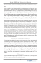
INSTALLATION PROCEDURES 4.2.6 Side Reach. If the clear floor space allows parallel approach by a person in a wheelchair, the maximum high side reach allowed shall be 54 inches (1370 mm) and the low side reach shall be no less than 9 inches (230 mm) above the floor (Fig. 6(a) and 6(b)). If the side reach is over an obstruction, the reach and clearances shall be as shown in Fig 6(c).
MODEL 8100 USER / INSTALLATION MANUAL Figure 5a. Forward reach, unobstructed. Figure 5b. Forward reach, obstructed. Figure 6a. Parallel approach - side reach. Figure 6b. Parallel approach - high/ low side reach. Figure 6c. Side reach, obstructed.
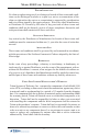
INSTALLATION PROCEDURES Figure 7. Handicap access area.
MODEL 8100 USER / INSTALLATION MANUAL THIS PAGE INTENTIONALLY LEFT BLANK A-10
INSTALLATION PROCEDURES ENVIRONMENTAL AND POWER CHECKLIST A-11
MODEL 8100 USER / INSTALLATION MANUAL When installing an ATM, some general environmental and power precautions need to be considered. Evaluate the location where the ATM will be installed. To help ensure proper operation of the ATM, ensure the environmental criteria listed in this checklist are met. TEMPERATURE/HUMIDITY 1. The ATM will operate over a range of temperatures and humidity.
INSTALLATION PROCEDURES CABINET (W/PLINTH) DIMENSIONS A-13
MODEL 8100 USER / INSTALLATION MANUAL Note All dimensions listed comply with US Federal ADA Guidelines. For USA installations, check for additional guidance. For non-USA installations, check regulations relating to the country of install. Dimensions in brackets measured in millimeters (mm).
INSTALLATION PROCEDURES Cabinet (w/signage) Cabinet (side view) A-15
MODEL 8100 USER / INSTALLATION MANUAL Cabinet (rear view) A-16
INSTALLATION PROCEDURES PLINTH / CABINET / DISPENSER INSTALLATION A-17
MODEL 8100 USER / INSTALLATION MANUAL PLINTH INSTALLATION The following procedure applies to installing the plinth assembly using either standard (P/N 06200-00066) or chemical (06200-00060) anchor kits. The anchor kits are not supplied with the unit.
INSTALLATION PROCEDURES 5. Stand the unit(s) up and walk them out of the shipping carton. 6. Remove the wrapping from the ATM. 7. Use the silver key to unlock both the control panel and the fascia door (which conceals the locking mechanism) on the front of the cabinet. Open the fascia door. 8. Turn the knob to open the front enclosure door.
MODEL 8100 USER / INSTALLATION MANUAL SELECTING THE INSTALLATION LOCATION Choosing the right location for your ATM is very important. Security concerns suggest a location that is away from any door or external access point. Ideally, the terminal should be mounted as close to a back wall as possible. For marketing reasons, however, it may be desirable to locate the terminal near the front where your customers can easily locate it.
INSTALLATION PROCEDURES TOOL USE/SAFETY Observe ALL safety precautions for operating hand and power tools! Wear eye and ear protection while operating the electric drill! CONCRETE STRENGTH The floor at the installation location should consist of commercialgrade concrete measuring at least 2000 psi in compression strength.
MODEL 8100 USER / INSTALLATION MANUAL Install Standard Anchors Bolt Plinth to Floor 1. Move the plinth into position for mounting by aligning the base over the four holes drilled in the previous procedure. 2. Place an anchor bolt through the plinth base and into one of the mounting holes. Use a ball peen hammer to tap the bolt completely into the hole.
INSTALLATION PROCEDURES Install Chemical Anchors Bolt Plinth to Floor 1. Move the plinth into position for mounting by aligning the base over the four holes drilled in the previous procedure. 2. Begin by inserting a Chem Stud capsule into one of the mounting holes. Either end of the capsule may be inserted first. 3. Place a washer and a nut (in that order) onto a chisel point rod. Thread the nut onto the rod, leaving 3 to 4 threads exposed. 4.
MODEL 8100 USER / INSTALLATION MANUAL 7. Pull the driver out of the coupling while holding the rod. Hold the hex nut with a wrench to unthread the coupler. 8. Repeat steps 1-7 for each of the remaining mounting holes. 9. Allow the adhesive to cure for the specified time (see chart and important not, which follow) prior to applying any load to the anchors.
INSTALLATION PROCEDURES Mount/Install ATM TOOLS: #2 Phillips screwdriver 7/16" nutdriver or equivalent NOTICE It is highly recommended that steps requiring lifting of the ATM cabinet be performed by 2 personnel. Before mounting the ATM cabinet to the plinth, some preliminary steps may be helpful for ease of installation. ! Lift/place the ATM cabinet on a table, bench, etc. Open the security door and slide the dispenser tray out fully. This will be temporarily removed.
MODEL 8100 USER / INSTALLATION MANUAL ! Using a phillips screwdriver, remove the two (2) front screws that secure the rail assemblies; retain screws. Next, loosen the back screws. Loosen Remove ! Pivot each slide rail slightly inward. This will allow easier access to secure the nuts to the plinths mounting screws when installing the ATM cabinet.. 1. Lift the ATM cabinet and mount on the plinth assembly’s four (4) mounting screws.
INSTALLATION PROCEDURES 2. Secure the assemblies together using the four (4) nuts provided with a 7/ 16" nutdriver or equivalent. ATM cabinet 3. Pivot the slide rail assemblies back and secure/tighten all screws previously removed/loosened. 4. Route the ATM power and phone line cables through the cabinet access hole into the plinth assembly. Pull the cables out through the rear access hole of the Nut plinth. Plinth (side view of mounting screws) Suggestion Route cables 5.
MODEL 8100 USER / INSTALLATION MANUAL INSTALLING THE TDM-50 DISPENSING MECHANISM TDM-50 1. Refer to Figure 1. Unlock and open the control panel. Verify that the power switch is in the OFF (0) position. Close the control panel. Four, 6-32 x 5/16 phillips screws (02054-00098) are required to attach the dispensing mechanism to the mounting tray. The screws are preinstalled on the tray. 3. Mounting tray. Using a phillips screwdriver, remove the front two (2) screws and loosen the rear 2.
INSTALLATION PROCEDURES 4. Place the TDM-50 on the 5. mounting tray with the cassette facing into the security cabinet. Align and slide the slots on the rear bottom of the dispenser under the two (2) screws previously installed (Figure 4). Install the two (2) front phillip screws back into the holes at the front of the dispenser shown in Figure 5. Tighten all the screws. Figure 5. Install front mounting screws. 6.
MODEL 8100 USER / INSTALLATION MANUAL THIS PAGE INTENTIONALLY LEFT BLANK A-30
INSTALLATION PROCEDURES POWER AND COMMUNICATION A-31
MODEL 8100 USER / INSTALLATION MANUAL ROUTE /CONNECT AC POWER AND TELEPHONE LINE 1. Ensure the power and phone cables are routed through the cabinet access hole as shown in Figure 1. 2. Route the AC power cord and the phone cord through either the plinth or alternate access hole (as applicable) as shown in Figure 2. 3. Connect the AC power cord and phone cable to their respective facility outlets. 4. Open the control panel and turn the power switch ON (I). Figure 1. Power/phone cable routing.
APPENDIX B COMBINATION LOCKS B-1
MODEL 8100 USER / INSTALLATION MANUAL INTRODUCTION The security cabinet can be secured using either a mechanical or electronic combination lock. This appendix covers how to change the combination of either lock. Procedures specific to the electronic lock, such as changing the battery, are also covered. The first section covers the Mechanical combination lock. OPERATING THE MECHANICAL LOCK UNLOCKING THE LOCK There are two marks on the dial ring (see drawing opposite page).
COMBINATION LOCKS Opening Index Changing Index Changing the Combination CHANGE THE COMBINATION: To change the combination, you will need access to the existing combination and a change key. First, open the safe door by dialing the existing combination. With bolt retracted and before changing combination, verify that the dial stopped between 90 and 100 on the ‘Opening Index’. Select three new numbers. DO NOT use any number between 1 and 20 for the last number.
MODEL 8100 USER / INSTALLATION MANUAL Figure 1 3. Turn change key to the Left until it stops (approximately one-quarter turn). With the change key in this position, set the new combination as follows: Note: Never select a number from 0 to 20 (the forbidden zone) as the last number of the combination. 4. Using the ‘Change Index’, turn the dial to the Left stopping when the first number of the new combination aligns with the ‘Change Index’, the Fourth time. 5.
COMBINATION LOCKS OPERATING THE ELECTRONIC LOCK The electronic lock combination consists of six digits. Upon arrival, the combination of the lock should already be preset to 1-2-3-4-5-6. ENTERING THE COMBINATION 1. Enter the preset combination and check for proper operation. After each keypress, the lock will beep. After the final digit has been entered, the lock will beep twice, and the open period will begin. 2.
MODEL 8100 USER / INSTALLATION MANUAL BATTERY LOW WARNING Repeated beeping during an opening indicates that the battery is low or dead and needs to be replaced. The battery box is located on the inside of the door. Note: If the lock will not operate (i.e. repeated beeping or no beeping) while the door is closed and locked, the battery must be energized from the two external terminals on the front of the push-button panel.