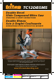
TC12DBSMS Double Bevel Slide Compound Mitre Saw OPERATING & SAFETY INSTRUCTIONS Double Biseau Scie à Onglet Coulissante INSTRUCTIONS D’UTILISATION ET DE SÉCURITÉ Thank you for purchasing this Triton power tool. These instructions contain information necessary for safe and effective operation of this product. Keep this manual close to hand and ensure all users of this tool have read and fully understand them. Merci d’avoir acheté cet outil électrique Triton.
FEATURES CONTENTS 2 3 4 7 8 14 17 18 18 Specifications Features Safety Symbols Functions Operation Service Warranty Triton offices 2 29 16 4 9 39 Model No: TC12DBSMS Voltage: 120V ~ 60Hz Input Power: 15 Amp No Load Speed: 5,000 RPM Blade Size: 12” (305mm) Bore Size: 1” (25.4mm) Number of Teeth: 60 Mitre Table Angles: 0° to 52° left & right Bevel Cuts: 0° to 45° left & right Net Weight: 47.3 lbs (21.
GENERAL SAFETY INSTRUCTIONS WARNING. Read and understand all instructions. Failure to follow all instructions listed below, may result in electric shock, fire and/or serious personal injury. Save these instructions. GB 1. Keep guards in place and in working order. 2. Remove adjusting keys and wrenches. Form habit of checking to see that keys and adjusting wrenches are removed from the tool before turning it on. 3. Keep work area clean. Cluttered areas and benches invite accidents. 4.
• Do not slow or stop a blade with a piece of wood. Let the blade come to rest naturally. • If you are interrupted when operating the saw, complete the process and switch off before looking up. • Periodically check that all nuts, bolts and other fixings are properly tightened. • Always hold the saw on parts that are insulated. If you accidentally cut into hidden wiring or the saw’s own cable, the metal parts of the saw will become ‘live’. Switch off at the mains and remove the plug immediately.
RELEASE KNOB FUNCTIONS ACCESSORIES TRANSPORT The TC12DBSMS mitre saw is supplied with the following accessories as standard: • Stabiliser bar (fitted) Lift the mitre saw only when the saw arm is locked in the down position, the saw is switched off and the plug is removed from the power point. Only lift the saw by the carrying handle (8) or outer castings. Do not lift the saw using the guard or operating handle (7).
ROTATING LOWER BLADE GUARD The rotating lower blade guard (12) provides protection from both sides of the blade. It retracts over the upper blade guard (9) as the saw is lowered into the workpiece. DUST BAG The dust bag (15) fits over the dust extraction port (27). For more efficient operation, empty the dust bag when it is no more than half full. This allows better air flow through the bag. ATTACHING THE SIDE BARS The side support bars (36) help to support the material when working with long workpieces.
SETTING THE FENCE SQUARE WITH THE TABLE 1. Make sure that the electrical plug is removed from the power point. 2. Push the saw arm (5) down to its lowest position and engage the release knob (6) to hold the saw arm in the transport position. 3. Loosen the mitre lock (25). 4. Rotate the table (21) until the pointer is positioned at 0°. 5. Tighten the mitre lock (25). 6. Using the 6mm hex key loosen the hex screw securing the top piece of the right hand side fence and remove this top section. 7.
BEVEL CUT OPERATION CROSS-CUTTING (WITHOUT SLIDE ACTION) When cutting a narrow piece of wood it is not necessary to use the slide mechanism. In these cases ensure that the slide lock (29) is screwed down to prevent the saw arm from sliding. A crosscut is made by cutting across the grain of the workpiece. A 90° crosscut is made with the mitre table set at 0°. Mitre crosscuts are made with the table set at some angle other than zero. 1.
6. Place the workpiece flat on the table with one edge securely against the fence (19). If the board is warped, place the convex side against the fence. If the concave side is placed against the fence, the board could break and jam the blade. 7. When cutting long pieces of timber, support the opposite end of the timber with the side bars (36), a roller stand or a work surface that is level with the saw table. 8. Use the clamp assembly (10) to secure the workpiece wherever possible. 9.
WARRANTY To register your warranty visit our web site at www.triton.com.au and enter your details. Your details will be included on our mailing list (unless indicated otherwise) for information on future releases. Details provided will not be made available to any third party. PURCHASE RECORD Date of Purchase: ___ / ___ / ____ Model: TC12DBSMS Serial Number: __________________ (Located on motor label) Retain your receipt as proof of purchase Triton Manufacturing & Design Co.
SOMMAIRE NOMENCLATURE 20 21 22 26 26 33 36 37 37 Caractéristiques Nomenclature Sécurité Symboles Fonctions Opération Réparation Garantie Bureaux de Triton 2 29 16 4 9 39 Modèle : TC12DBSMS Voltage : 120 V ~ 60 Hz Puissance d’entrée : 15 A Vitesse à vide : 5 000 tr/min Lame : 12” (305 mm) Trou : 1” (25,4 mm) Nombre de dents : 60 Angles de table à onglets : 0° à 52° gauche et droite Coupe en biseau : 0° to 45° gauche et droite Poids net : 47,3 lbs (21,5 kg) 8 12 14 13 27 30 32 28
INSTRUCTIONS DE SÉCURITÉ GÉNÉRALES AVERTISSEMENT ! Veuillez lire et comprendre toutes les instructions. Le non-respect des instructions ci-dessous peut entraîner des chocs électriques, des incendies ou des blessures graves. F Conservez ces instructions. 1. Gardez les protège-lames en place et en bon état. 2.Retirez les clés de réglage avant d’utiliser l’outil. Prenez l’habitude de vérifier si les clés sont retirées de l’outil avant de le faire fonctionner. 3. Veillez à ce que l’aire de travail soit propre.
F • Assurez-vous que l’outil soit fixé à un établi lorsque possible. • Tenez-vous de côté lors de l’utilisation de la scie. • N’utilisez jamais de lame fissurée ou tordue. Utilisez toujours une lame affûtée. • Lors de la coupe de bois rond, utilisez des serres pour empêcher le bois de tourner. • N’utilisez jamais vos mains pour retirer des poussières, des copeaux ou d’autres déchets près de la lame. • Utilisez seulement des lames recommandées par le fabricant et conformes aux normes EN 847-1.
RALLONGES • Remplacez les cordons endommagés immédiatement. L’utilisation de cordons endommagés pourrait entraîner des chocs, des brûlures ou des électrocutions. • En cas de besoin d’une rallonge, utilisez un cordon de calibre adéquat afin d’éviter toute chute de tension, perte de courant ou surchauffe. Le tableau suivant indique les calibres recommandés pour les rallonges en fonction de leur longueur et de la tension nominale de l’outil. Si vous avez un doute, optez pour le prochain calibre.
AVERTISSEMENT ! Assurezvous de bien verrouiller les serrures de la table à onglets avant d’effectuer une coupe. Le non-respect de cette précaution entraînera un déplacement de la table durant la coupe, causant possiblement des blessures graves. ASSEMBLAGE DES BRIDES DE FIXATION INSTALLATION DES BARRES LATÉRALES Les brides de fixation (10) peuvent être installées sur le guide ou de chaque côté de la lame, selon la tâche effectuée.
6. Relâchez le verrouillage de biseau (16) et placez le bras de la scie (5) au biseau 0º (la lame étant à 90º avec la table à onglets). Serrez le verrouillage de biseau (16). 9 0° 7. Placez une équerre contre la table (21) et la partie droite de la lame. NOTE: Assurez-vous que l’équerre soit en contact avec la partie droite de la lame et non les dents. 8. Tournez la lame à la main et vérifiez l’alignement de la lame à la table à différents endroits. 9.
7. Maintenez le protège-lame rotatif (12) soulevé et appuyez sur le bouton de verrouillage de l’arbre (26). Tournez la lame jusqu’à ce que l’arbre se verrouille. 8. À l’aide de la clé hexgonale 6mm fournie, enlevez le boulon de la lame (dévissez dans le sens des aiguilles d’une montre. La vis est filetée à gauche). 9. Retirez la rondelle plate, la rondelle extérieure de la lame et la lame. 10.
3. Appuyez sur le loquet de relâchement, abaissez la lame vers la pièce. En même temps, faites-la glisser loin de vous jusqu’à ce que la pièce soit complètement coupée. 4. Relâchez l’interrupteur (24) et laissez la lame arrêter de tourner avant de retirer la lame de la pièce. Attendez que la lame s’arrête avant de retirer la pièce. COUPE EN BISEAU Une coupe en biseau est faite en coupant à travers le grain de la pièce, avec la lame à un angle déterminé avec le guide et la table à onglets.
6. Lorsque la lame atteint sa vitesse maximale (environ 2 secondes), abaissez la lame sur la pièce. 7. Une fois la coupe complétée, éteignez le laser en appuyant sur l’interrupteur du laser (2). 8. Après chaque usage, nettoyez l’assemblage de la ligne laser (1) de la façon suivante: 9. Éteignez le laser en appuyant sur l’interrupteur laser (2) et mettez l’outil hors tension. 10.
F F 38 39
40