
Owner Manual

Triton Systems ©
18
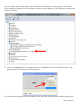
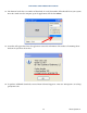
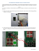
10. Unplug the red/blue wire on cable harness from the count sensor emitter board.
11. Remove emitter board by removing screw and routing board out through opening. Retain screw for reinstal-
lation.
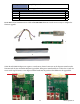
12. Remove new emitter board from upgrade kit. Slide emitter board into opening and align notch into right-
side hole.
13. Secure emitter board with screw removed in step 11.
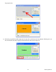
14. Unplug the black/yellow wire on cable harness from the count sensor receiver board.
15. Remove receiver board by removing screw and routing board out through opening. Retain screw for reinstal-
lation.
receiver
emitter
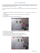
**Note**
e rubber cover on the sensor closest to the receiver board screw may need to be removed for receiver board
installation. Replace rubber cover aer installation.
16. Remove new receiver board from upgrade kit. Slide receiver board into opening and align notch into le side
hole.
17. Secure receiver board with screw removed in step 15.
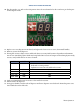
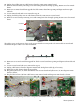
18. Unplug cable harness from the dispenser main board. Unclip from cable clip, if necessary.
19. Remove new cable harness from the upgrade kit.
20. Plug black/yellow wire (A) from cable harness into receiver board and yellow wire (A) into dispenser main
board, as shown.
21. Plug the blue/red wire (B) from cable harness into emitter board and dispenser main board, as shown.
A
A
B
B
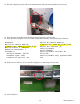
22. Reconnect the dispenser power cable to dispenser and available outlet or power supply.