INSTALLATION MANUAL AUSTRALIAN DISPENSER UPGRADE ©2018 Triton Systems of Delaware, LLC. All Rights Reserved. ATMGurus®, the ATMGurus logo and tagline, Triton®, and the Triton logo are all registered trademarks of Triton Systems of Delaware, LLC. The third party trademarks that may be identified herein are the trademark of their respective owners.
revision history October 30, 2018 November 26, 2018 Add TDM guide rail settings for polymer notes Add MiniMech upgrade kit ECO 1032221 Contact Information Triton© 21405 B Street Long Beach, MS 39560 USA 1 (877) 787-4866 1 (228) 575-3100 (228)575-3101 (fax) customer.service@atmgurus.com www.atmgurus.
table of contents revision history...................................................................................................................2 contact information..........................................................................................................2 purpose...................................................................................................................................2 table of contents.............................................................................
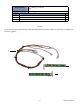
Required Tools Kit 41017-00006 Part # 1 2 3 No. 2 Phillips screwdriver Snips HCDU Upgrade Kit Double detect emitter board Double detect receiver board Cable harness Description Qty 1 1 1 **Note** 09120-00923 Serial Communication Cable and 06300-00007 Firmware Loader are necessary to complete the firmware upgrade.
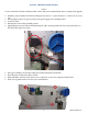
install the hcdu upgrade kit **Note** Service technician will need a firmware loader comloc and serial communication cable to complete this upgrade. 1. Perform a proper shutdown of ATM via Management Functions > System Parameters > Shut Down the Terminal. 2. When prompted, place the power switch on the power supply to the off (O) position. 3. Access the vault. 4. Pull dispenser out to fully extended position. 5. Unplug dispenser power cable and communications cable.
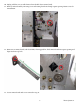
10. Unplug red/blue wire on cable harness from double detect emitter board. 11. Remove emitter board by removing screw and routing board out through square opening. Retain screw for reinstallation. 12. Remove new emitter board (with clear LEDs) from upgrade kit. Slide emitter board into square opening and align notch into top hole. 13. Secure emitter board with screw removed in step 11.
14. Unplug the yellow/black wire on cable harness from double detect receiver board. 15. Remove receiver board (with black sensors) by removing screw and routing board out through square opening. Retain screw for reinstallation. 16. Remove new receiver board (with black sensors) from upgrade kit. Slide receiver board into square opening and align notch into bottom hole. 17. Secure receiver board with screw removed in step 15.
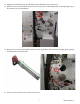
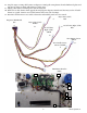
18. Snip TY wraps securing cable harness to dispenser. Gently pull wiring harness from behind metal plates and snip any TY wraps securing cable harness to other wires. 19. Unplug cable harness from dispenser main board at JP8. 20. Remove new cable harness from upgrade kit and plug into dispenser main board. You may use the old cable harness as a guide. Connect rest of cable harness and secure with TY Wraps. 21. Reconnect the dispenser power cable to dispenser and available outlet or power supply.
upgrading cdu firmware using pc loader utility A serial communication cable (p/n 09120-00923) is required to download the firmware from the PC to the serial CDU dispenser. If your PC does not have a serial port, you will also require a USB-to-serial adapter (p/n 0126000019). **Note** Screen shots are indicative of what should be seen during the load process. Firmware versions and actual screens may vary. 22. Unplug the unit data cable from the dispenser, if necessary.
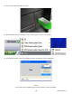
24. Insert comloc into the USB slot on PC. 25. Run the utility loader by clicking on Start > All Programs > Triton > CDU Load. 26. In the drop down box, choose the COM port where the dispenser cable is plugged in. **Note** Screen shots are for example purposes only. Firmware version may differ.
If you are using a USB-to-serial adapter, you can determine the COM port to use by going to Control Panel > Device Manager in Windows. Locate the USB-to-serial device name under ports. The COM port associated with this device is shown. 27. Choose “scdu(0910XX).bin” for a SCDU Dispenser or “hcdu(0b12XX).bin” for an HCDU dispenser. The green progress bar will advance as the load proceeds. 28. Click Start. The program will load onto dispenser.
the program runs. 29. When the program has loaded completely, the status bar at the bottom will state Success. The dispenser can now be disconnected safely. Unplug the download data cable from the dispenser.
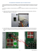
reinstall hcdu dispenser 30. Flip dip switches 1, 3, and 4 to the ON position. Press the reset button below the switches to put the dispenser into dispense mode. 31. Replace cover over dispenser main board, and tighten the four screws to secure, then install handles. 32. Remove cassettes from dispenser. 33. If using old cassettes, adjust cassette width rails where necessary. Rail location is dependent on denomination of new Australian polymer bank note being loaded into cassette.
37. Reconnect dispenser power cable and communications cable. Reattach ground wire if necessary. 38. If the dispenser is installed in an ATM at the time of upgrade, restart the unit. 39. Once the load is complete, review the ATM configuration summary. Verify the dispenser firmware. Dispenser Device ID: Hantle MCDU-H1 Firmware Ver: MCDU-H1-U2-0B.12.69 Device Status: 0 (Success) Number of Cassettes: 3 Cassette A Multiple Amount: $10.
updating cdu firmware license 42. The firmware loader has a set number of downloads. To verify the number of downloads left on your system, insert the comloc into the computer, open the application, then click on About. 43. A window will appear that shows the application version for information. The number of remaining downloads on the systems is shown here. 44. To purchase additional downloads, contact Triton Technical Support at 1-866-787-4866 option 4, or techsupport@triton.com.
Required Tools No. 2 phillips screwdriver Kit 41017-00005 SCDU Upgrade Kit Part # 1 2 3 4 Description Qty 1 1 1 1 Count sensor emitter board Count sensor receiver board Cable Spacers **Note** 09120-00923 Serial Communication Cable and 06300-00007 Firmware Loader are necessary to complete the firmware upgrade. 1 3 2 4 SCDU II and SCDU III dispensers require a second sensor channel connector on the dispenser main board to function with the New Australian Polymer Upgrade Kit.
install scdu upgrade kit A serial communication cable (p/n 09120-00923) is required to download the firmware from the PC to the serial CDU dispenser. If your PC does not have a serial port, you will also require a USB-to-serial adapter. Both parts are readily available at local electronics stores. **Note** Screen shots are indicative of what should be seen during the load process. Firmware versions and actual screens may vary. 1.
10. Unplug the red/blue wire on cable harness from the count sensor emitter board. 11. Remove emitter board by removing screw and routing board out through opening. Retain screw for reinstallation. 12. Remove new emitter board from upgrade kit. Slide emitter board into opening and align notch into rightside hole. 13. Secure emitter board with screw removed in step 11. 14. Unplug the black/yellow wire on cable harness from the count sensor receiver board. 15.
upgrading cdu firmware using pc loader utility A serial communication cable (p/n 09120-00923) is required to download the firmware from the PC to the serial CDU dispenser. If your PC does not have a serial port, you will also require a USB-to-serial adapter (p/n 0126000019). **Note** Screen shots are indicative of what should be seen during the load process. Firmware versions and actual screens may vary. 23. Unplug the unit data cable from the dispenser if not already done.
25. Insert comloc into the USB slot on PC. 26. Run the utility loader by clicking on Start > All Programs > Triton > CDU Load. 27. In the drop down box, choose the COM port where the dispenser cable is plugged in. **Note** Screen shots are for example purposes only. Firmware version may differ.
If you are using a USB-to-serial adapter, you can determine the COM port to use by going to Control Panel > Device Manager in Windows. Locate the USB-to-serial device name under ports. The COM port associated with this device is shown. 28. Choose “scdu(0910XX).bin” for a SCDU Dispenser or “hcdu(0b12XX).bin” for an HCDU dispenser. The green progress bar will advance as the load proceeds. 29. Click Start. The program will load onto dispenser.
the program runs. 30. When the program has loaded completely, the status bar at the bottom will state Success. The dispenser can now be disconnected safely. Unplug the download data cable from the dispenser and reattach the unit’s data cable.
reinstall scdu dispenser 31. Flip dip switches 1, 2, and 4 to the ON position. Press the reset button near the switches to put the dispenser into dispense mode. 32. Replace cover over dispenser main board, then tighten the four screws to secure. 33. If it will be loaded with AUD $5.00 notes, remove the cassette from dispenser. If a new cassette was purchased, skip to step 35. 34. Install the spacers by removing the adhesive backing and mounting spacer to side of black rails as shown below.
37. Reconnect dispenser power cable and communications cable. 38. Place dispenser into vault. Ensure slots line up with mounting holes on tray within vault. 39. 40. 41. 42. Secure with screws removed in step 5. Close vault door. Place the power switch on the power supply to the on (I) position. Once the load is complete, review the ATM configuration summary. Verify the dispenser firmware. Dispenser Device ID: Hantle H1 Firmware Ver: H1-09.10.
updating cdu firmware license 43. The firmware loader has a set number of downloads. To verify the number of downloads left on your system, insert the comloc into the computer, open the application, then click on About. 44. A window will appear that shows the application version for information. The number of remaining downloads on the systems is shown here. 45. To purchase additional downloads, contact Triton Technical Support at 1-866-787-4866 option 4, or techsupport@triton.com.
Required Tools Torx T10 screwdriver Torx T20 screwdriver Kit 06200-00390 NMD 50 Upgrade Kit Part # 1 2 CMC 50 Rev 4 NFC 200 Rev 5 Description Qty 1 2 2 1 2 **Note** NMD 50 Rev 1 or Rev 2 dispensers must be replaced with a newer model due to the number of component changes. Only dispenser revisions 3, 4, and 5 can be upgraded for the new Australian polymer notes. Revision ID plate is located on metal frame under the cassette in the top feed channel.
installing nmd 50 upgrade kit 1. Perform a proper shutdown of ATM via Management Functions > System Parameters > Shut Down the Terminal. 2. When prompted, place the power switch on the power supply to the off (O) position. 3. Access the vault. 4. Pull dispenser out to fully extended position. Identify dispenser revision. Revision ID plate is located on metal frame under cassette in the top feed channel. 5. Unplug dispenser power cable and communications cable. 6.
8. Disconnect cable harnesses from CMC board. 9. Using a Torx T10 screwdriver, remove screw from top of CMC cover. Retain for reinstallation. Note any ground wires that are unattached during screw removal. CMC NFC NFC NMD 50 ** Note ** Only Rev 4 boards can be used for this upgrade. Verify new CMC board is a Rev 4. 10. Remove new CMC board from upgrade kit. 11. Plug cable harnesses into new CMC board. 12. Slide CMC board into place on dispenser and install screw removed in step 9 to secure CMC board.
13. Using a Torx T10 screwdriver, remove screw from top of NFC board on channel 1. Retain for reinstallation. Note any ground wires that are unattached during screw removal. CMC NFC NFC NMD 50 ** Note ** Only Rev 5 boards can be used for this upgrade. Ensure new NFC boards are Rev 5. 14. Remove new NFC board from upgrade kit. 15. Plug cable harnesses into new NFC board. 16. Slide NFC board into place on dispenser and install screw removed in step 13 to secure NFC board.
Required Tools Kit 06200-00390 Part # 1 2 3 4 5 Torx T10 screwdriver Torx T20 screwdriver Flat head screwdriver Snips NMD 100 Upgrade Kit CMC 200 Rev 3 NFC 200 Rev 5 Mechanical sensor Lever Spring Description Qty 1 2 1 1 1 2 2 5 4 3 1 **Note** NMD 100 Rev 8 or earlier dispensers must be replaced with a newer model due to the number of component changes. Only dispenser revisions 9 through 12 can be upgraded for the new Australian polymer notes.
installing nmd 100 upgrade kit 1. Unlock cassettes via Management Functions > Terminal Configuration > Cassette Setup > Cassette Parameters. Uncheck All Cassettes Locked option, then choose OK on the warning screen. 2. Remove cassettes from dispenser. 3. Place power switch on the dispenser power supply to the off (O) position. 4. Using a Torx T20 screwdriver, remove the top cover from the dispenser. Retain screws for reinstallation. 5.
9. Unplug the following cable harnesses: —— CAN com to first feeder at upper NFC board —— NFC power cable at upper NFC board —— Dispenser power cord at power supply —— Note stacker stepper motor cable at motor —— All connections at CMC board 10. Using a Torx T10 screwdriver, remove three screws from CMC board. Retain for reinstallation. Note any ground wires that are unattached during screw removal. ** Note ** Only Rev 3 boards can be used for this upgrade. Verify new CMC board is a Rev 3. 11.
** Note ** Only Rev 5 boards can be used for this upgrade. Ensure new NFC boards are Rev 5. 14. Remove new NFC board from upgrade kit. 15. Slide NFC board into place on dispenser and install screw removed in step 13 to secure NFC board. Ensure any necessary ground wires are reattached. 16. Repeat steps 13-16 to replace NFC board in channel 2 and for any additional channels. 17. Using a Torx T20 screwdriver, remove two screws on each side of dispenser along the top edge of the upper feed channel.
21. Remove note stacker by inserting hands into the second and fourth openings of the note stacker and pressing tabs inwards until component releases. 22. Using a Torx T10 screwdriver, loosen three screws on note stacker motor. 23. Reach in to the fifth opening and remove the note stacker timing wheel cover by gently squeezing sides and sliding out. tabs note stacker timing wheel cover 24. Using needle nose pliers, remove the gold t-bar in the center opening and the wheel assembly underneath.
27. Using diagonal snips, trim the rib on the prism, then file smooth. 28. Remove rubber plug on note stacker, then flip back over. Retain plug for reinstallation. 29. Reinstall the wheel assembly with flat side up and gold t-bar removed in step 24. 30. Remove mechanical sensor base from upgrade kit, and route wire through openings in the bottom side of note stacker. 31. Replace rubber plug removed in step 21 to secure cables in place.
32. Insert mechanical sensor base and snap down over gold t-bar. 33. Gently place spring from upgrade kit into round opening on mechanical sensor base. 34. Remove lever arm from upgrade kit and route hooked end through the opening between wheel and mechanical sensor so that hooked end rests under metal axle of wheel assembly. 35. Notch on opposite end of lever arm will rest in the top of spring and round tabs of lever arm will align with notched opening in center of mechanical sensor. 36.
39. Install the small belt removed in step 20. 40. Replace upper portion of dispenser, ensuring tabs slide into notches. 41. Using a Torx T20 screwdriver, install two screws removed in step 10 on each side of dispenser along the top edge of the upper feed channel. 42.
21. Secure all wires and cables in white cable clips along the top of the upper feed channel. 22. Hold side cover near side of dispenser and slide ground wires onto metal tabs inside cover. 23. Attach side cover with five screws removed in step 6. 24. Attach handles on each side of dispenser with screws removed in step 5. 25. Attach top cover with two screws removed in step 4.
Required Tools Kit 06200-00419 Part # 1 Torx T15 screwdriver No.
installing sdd upgrade kit 1. Perform a proper shutdown of ATM via Management Functions > System Parameters > Shut Down the Terminal. 2. When prompted, place the power switch on the power supply to the off (O) position. 3. Access the vault. 4. Pull dispenser out to fully extended position. 5. Using a Torx T15 screwdriver, remove the two screws on each side that secure the front bracket. Retain for reinstallation. Remove bracket from dispenser. 6. Using a No.
12. Install bracket on dispenser by sliding mylar exit sensor behind the exit sensor and rotating bracket down into place. top view front view 13. Secure with screws removed in step 5. 14. Push dispenser back into ATM and close vault. 15. Place power switch on ATM power supply to the on (I) position.
install tdm upgrade Required Tools Part # 1 TDM load cable Firmware loading comloc TDM Upgrade TDM firmware loader Description **Note** Firmware version may differ from what is shown. Qty 1 1. Before starting installation of TDM Firmware Loader, unplug the comloc from the PC and the data cable from the dispenser. 2. On PC, browse to the location where the TDMFirmwareLoaderSetup.exe file is saved. Double-click the file to start the installation process. The following window will appear: 3.
update tdm firmware via tdm firmware loader **Note** Firmware versions may be different than what is shown. 6. Insert the comloc in a USB port on the PC. 7. Click the TDM Firmware Loader icon on the desktop to launch the application. 8. When the application launches, the following warning will appear. Ensure the dispenser is powered off, and the data cable and power cable are disconnected from the TDM, then click OK. 9. The TDM Firmware Loader application will open. 10.
**Note** Newer PCs or laptops may not have serial ports, and require a USB-to-Serial adapter. If using a USB-to-Serial adapter, you can determine the correct COM port by navigating to the Control Panel, then to Device Manager in Windows. Locate the USB-to-Serial device name under ports. The COM port associated with device is shown.
11. Click Next or Previous to toggle through TDM models. Click on the picture that matches your TDM dispenser. 12. Verify that TDM matches the photo in the pop-up window that appears. 13. Click Yes if the picture matches TDM dispenser. Click No to return to the previous screen and select another dispenser. 14. After clicking Yes, connect dispenser power cable. Turn power to the dispenser on (I), then click OK.
15. Connect the data cable to load port on the dispenser, then click OK. 16. Firmware loading should begin automatically. 17. Power down dispenser and disconnect the data cable from the TDM, then click OK. 18. Apply power to the dispenser. 19. After motor stops turning, reconnect the data cable to the TDM, then click OK.
20. Enter TDM serial number as printed on the TDM label. Use capital letters as printed on the label. Click OK. 21. The TDM Firmware Loader will report a successful download. Click OK. 22. Power off the dispenser, then disconnect the data cable.
update tdm firmware license 1. The TDM Firmware Loader has a set number of downloads. To verify the number of downloads left on your system, open the application, then click Version. 2. A pop-up window will display application version information. The number of downloads left on the system is shown under Remaining Uses. 3. To purchase additional downloads, contact Triton Technical Support at 1 877-787-4866. 4. Click Update License. 5.
adjust tdm cassette guide rails 1. Adjust cassette width and height rails where necessary. Rail location is dependent on denomination of new Australian polymer bank note being loaded into cassette. If using new Australian polymer-ready cassette, verify width rails are in correct location. Bank Note AUD $5 AUD $10 AUD $20 AUD $50 AUD $100 Left Guide H F F E D Right Guide N L I G F Height F F F F F 2. Load or replenish bank notes in cassettes. Close and lock cassettes. 3. Install cassettes in dispenser.
Required Tools Kit 04008-00060 Part # 1 2 3 bracket mylar tab screw Torx T10 screwdriver No 2 phillips screwdriver MiniMech Upgrade Kit Description Qty 1 1 1 3 1 4 2 50 Triton Systems ©
install the minimech upgrade kit 1. Perform a proper shutdown of ATM via Management Functions > System Parameters > Shut Down the Terminal. 2. When prompted, place the power switch on the power supply to the off (O) position. 3. Access the vault. 4. Using a No 2 phillips screwdriver, remove two screws securing dispenser to stationary tray. Retain for reinstallation. 5. Remove dispenser from vault and place on a flat work surface. 6. Remove bracket and mylar tab from kit. 7.
9. Remove screw from upgrade kit. Using a Torx T10 screwdriver, install screw into top of bracket. Tighten only enough to hold bracket to metal tab. 10. Install dispenser in ATM. 11. Secure dispenser to stationary tray using screws removed in step 4 and close vault. 12. Place power switch on ATM power supply to the on (I) position.