
Owner Manual

31
MODEL RT2000 (X2) INSTALLATION GUIDE
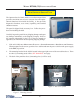
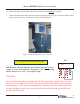
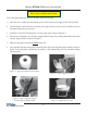
4. Mount the OSP so that the data cable will be connected on the bottom of the panel.
5. Connect the Data cable (RJ-45 connector end) to the OSP shown in Figure 3. Ensure the other end of
cable is connected to the “A
UXILLARY” port on the Docking board.
Figure 3. OSP mounted and cable connected.
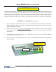
12V DTR
J11
IMPORTANT: The Rear Operator Service Panel (OSP) MUST have a
jumper set on the Docking Board. The jumper ( ‘J11’ on the Docking
Board) must be set to “12V”. See graphic at right.
CONFIGURE DOCKING BOARD JUMPER
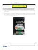
Inspect the Mounting Bracket Studs and RSP Mounting Holes closely. Note the studs
have grooves provided for the RSP to mount onto. Ensure the RSP sets down onto the
studs properly on all 3 (three) mounting points. Failure to do so may allow the RSP to
become dislodged, which may cause physical and electrical damage to the RSP and
possibly personal injury.