MODEL RT2000 (X2) AUTOMATED TELLER MACHINE SITE PREPARATION / INSTALLATION GUIDE TDN 07100-00097 Dec 11 2009 CORPORATE HEADQUARTERS 21405 B St. Long Beach, MS 39560 Phone: (228) 575-3188 Fax: (228) 575-3200 © 2009 Triton. All Rights Reserved. TRITON logo is a registered trademark of Triton Systems of Delaware.
MODEL RT2000 (X2) INSTALLATION GUIDE INTRODUCTION The Triton RT2000 is a self-serviced, weatherized terminal adaptable for any suitable exterior (or interior) wall or vestibule location. The cabinet design allows installation for maximum wall thickness up to 11-1/2” [279mm]. Built-in leveling feet and optional platforms (“plinths”) allow the unit to be raised to the desired height of the wall opening.
MODEL RT2000 (X2) INSTALLATION GUIDE CONTENTS SITE COMPLIANCE .........................................................................................................4 ENVIRONMENTAL PRECAUTIONS .....................................................................................5 TEMPERATURE / POWER / RF INTERFERENCE REQUIREMENTS.........................................................................6 DIMENSIONS.............................................................................................
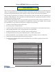
MODEL RT2000 (X2) INSTALLATION GUIDE SITE COMPLIANCE This document contains the information necessary for the preparation and installation of an RT2000 Triton electrical wiring and mechanical systems must also comply with all relevant laws and regulations. The site must be prepared by the customer or his agent who is fully conversant with the requirements of installing ATM equipment.
MODEL RT2000 (X2) INSTALLATION GUIDE ENVIRONMENTAL PRECAUTION CHECKLIST 5
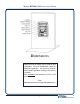
MODEL RT2000 (X2) INSTALLATION GUIDE When installing an ATM, some general environmental and power precautions need to be considered. Evaluate the location where the ATM will be installed. To help ensure proper operation of the ATM, ensure the environmental criteria listed are met. TEMPERATURE / HUMIDITY * IMPORTANT * AC power for the terminal should come from a dedicated source with an isolated ground. 1. The ATM will operate over a range of temperatures and humidity.
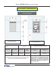
MODEL RT2000 (X2) INSTALLATION GUIDE DIMENSIONS Dimensions listed comply with US Federal ADA Guidelines. For USA installations, check for additional guidance. For non-USA installations, check regulations relating to the country of install. The maximum wall thickness is 11-1/2” (279 mm).
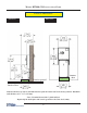
MODEL RT2000 (X2) INSTALLATION GUIDE WALL OPENING / TRIM DIMENSIONS This area must be free of obstruction for trim installation Exterior ground * ) + $ ) 34 5 6"789 :;<; = Exterior ground , - 2 / 48 5 ;">9 :<47 = .
MODEL RT2000 (X2) INSTALLATION GUIDE CUSTOMER ACCESS DIMENSIONS CABINET “FOOTPRINT” Note: Front of unit.
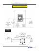
MODEL RT2000 (X2) INSTALLATION GUIDE PHYSICAL DIMENSIONS REAR VIEW SIDE VIEW 6” plinth } 6” plinth Exterior ground Interior ! ! ## $ #%&' &() ! " Note: Terminal shown with 6” plinth utilized.
MODEL RT2000 (X2) INSTALLATION GUIDE SERVICE AREA DIMENSIONS Ensure that doorways and corridors leading to the point of installation are wide enough to allow the shipping package to pass through. If access is restricted, make arrangements to unpack the unit in an area with } the unit. The service area dimensions and clearances recommended for the RT2000 cabinet installation.
MODEL RT2000 (X2) INSTALLATION GUIDE MINIMUM SERVICE CONFIGURATIONS 12
MODEL RT2000 (X2) INSTALLATION GUIDE INSTALLATION 13
MODEL RT2000 (X2) INSTALLATION GUIDE BEFORE YOU START ! } } securing the unit through the leveling feet “plinth” hardware, regardless of how high the unit may be raised.
MODEL RT2000 (X2) INSTALLATION GUIDE DETERMINE IF PLINTH REQUIRED Triton Systems offers two (2) metal-constructed optional plinths w/leveling feet. A “plinth” is a platform on which the ATM rests or is secured. A plinth enables the ATM to be installed at the required height through the wall. The plinths come in 2 heights: 3” [76mm] and 6” [152 mm - shown below]. You can raise the ! ~ `' *| plinths leveling feet.
MODEL RT2000 (X2) INSTALLATION GUIDE TOOLS / ITEMS REQUIRED % " ! Lifting/moving devices (pallet jack, forklift, lifting jack/trolley, etc) Crowbar / roll bars, scrap lumber (blocking) Tape measure / bubble level / framing square Hammer / chisel Back support belt / safety goggles,/mask steel-toed shoes Marker / pencil Tool kit consisting of: Adjustable wrench (large), box wrenches (open / closed) - up to 1-1/4” (32 mm)
MODEL RT2000 (X2) INSTALLATION GUIDE INSTALLING CABINET THROUGH WALL OPENING *** WARNING *** The RT2000 unit is top heavy. USE EXTREME CAUTION! Always move/support the unit from the FRONT! 2-personnel are recommended when unpacking and moving the unit!! 1. Carefully inspect the unit for any shipping damage and report any damage immediately to the shipping company. Refer to the warranty information in the User manual for information about reporting shipping damage. 2.
MODEL RT2000 (X2) INSTALLATION GUIDE 6. If a plinth is used (either built or purchased), mount the cabinet on the plinth. Anchor the cabinet to the plinth using the bolts provided (optional plinth) or secure to your built plinth. Tighten bolts enough to secure the two together for moving the unit.
MODEL RT2000 (X2) INSTALLATION GUIDE 10. < } ~ Control panel slots. Mount fascia trim to control panel. *** WARNING *** When removing/placing the unit on the plinth, be mindful that the unit is top-heavy. One person should support the front at all times! Take care not to damage the front of the sleeve as this has the control panel electronics and hardware mounted. 11.
MODEL RT2000 (X2) INSTALLATION GUIDE ADJUSTING HEIGHT/LEVEL OF UNIT Triton Systems offers two (2) metal-constructed optional plinths w/leveling feet. The plinths come in 2 heights: 3” (76 mm) and 6” (152 mm - shown below). Based on the height requirement needed, you can either: 1) Raise the unit with the leveling feet installed in the cabinet (Business and Level 1) using a 1/4” (6mm) nut driver/socket.
MODEL RT2000 (X2) INSTALLATION GUIDE INSTALLING / SECURING CONTROL PANEL TRIM 1. Loosen the three (3) thumbscrews on the backside of the fascia trim hardware. Loosen until the ends } Three (3) thumbscrew. 2. (Reference previous steps for mounting control panel trim) Align the trim clips with the sleeve slots and insert until the trim is seated on the control panel. 3. Once the trim is in place, open the rear cabinet door.
MODEL RT2000 (X2) INSTALLATION GUIDE 4. Connect the ground wire attached to the bill tray to the ground stud located on the inside left of the < Secure ground wire. Ground wire shipped with control panel trim. 5. Next, connect the power cable to the LED circuit board as shown below. Power cable (located in harness). Secure ground wire. 6.
MODEL RT2000 (X2) INSTALLATION GUIDE SEALING THE CONTROL PANEL TRIM To ensure that the temperature around the unit is maintained during cold weather, it’s important that the wall ! ! ! } between the ATM and the inside wall opening should be left clear to allow air to circulate at room temperature. After the control panel trim is installed, a good weather seal is needed between the exterior wall and the trim.
MODEL RT2000 (X2) INSTALLATION GUIDE THIS PAGE INTENTIONALLY LEFT BLANK 24
MODEL RT2000 (X2) INSTALLATION GUIDE ROUTE POWER AND COMMUNICATION CABLES 25
MODEL RT2000 (X2) INSTALLATION GUIDE Route AC Power and Communication Cable 4@2A1 , + 7 5 5 B + ! C 5 ! 55 + OFF D 5 0 5 5 ! 1. Open the vault cabinet door. Route the AC power cord and the phone (or Cat-5) cable through either the main or alternate cable access hole (as applicable). Install the supplied snap bushing into the access hole that carries the power and phone cords. 2.
MODEL RT2000 (X2) INSTALLATION GUIDE Power Outlet Accessibility Y ! X ~ outlet to supply power to the ATM, make sure the following requirements are met: 1. The outlet is located near the equipment. 2. AC power for the terminal should come from a dedicated source with an isolated ground. The ATM is designed to work on an IT (Isolated-Terra) type power system having a phase-to-phase voltage not exceeding 240 volts. 3.
MODEL RT2000 (X2) INSTALLATION GUIDE TCP/IP (ETHERNET) ! ; Q$$$ { ` { | Y { `Y { | capable. The ATM functions that are normally performed via the dial-up telephone system, such as customer transactions and remote monitoring, can be performed using existing in-house communications network. ATM transaction processing and hardware monitoring functions are performed across a shared network medium.
MODEL RT2000 (X2) INSTALLATION GUIDE OPERATOR SERVICE PANEL INSTALLATION 29
MODEL RT2000 (X2) INSTALLATION GUIDE REAR OPERATOR SERVICE PANEL The Operator Service Panel (OSP) is a touchscreen panel that provides convenient user-access to cassette close and replenishment functions from inside the facility. It also provides diagnostics functions, reset error(s) capability, and terminal shutdown/restarts. The panel is shipped in the accessory box. Follow the procedures for installing the OSP.
MODEL RT2000 (X2) INSTALLATION GUIDE 4. Mount the OSP so that the data cable will be connected on the bottom of the panel. 5. Connect the Data cable (RJ-45 connector end) to the OSP shown in Figure 3. Ensure the other end of cable is connected to the “AUXILLARY” port on the Docking board. Figure 3. OSP mounted and cable connected. CONFIGURE DOCKING BOARD JUMPER J11 12V DTR IMPORTANT: The Rear Operator Service Panel (OSP) MUST have a jumper set on the Docking Board.
MODEL RT2000 (X2) INSTALLATION GUIDE THIS PAGE INTENTIONALLY LEFT BLANK 32
MODEL RT2000 (X2) INSTALLATION GUIDE TDM-250 CASSETTE INSTALLATION 33
MODEL RT2000 (X2) INSTALLATION GUIDE INSTALLING TDM CASSETTE(S) The TDM-250 dispensing mechanisms are shipped mounted on the slide tray inside the security cabinet. The power, data, and ground cables are connected. The cassettes are shipped separately (currency/reject). 1. Remove the packing material from the cassettes. For the TDM -250, there are (2) currency and (1) reject cassette. 2. Insert the currency cassette(s) into its compartment(s) in the dispenser.
MODEL RT2000 (X2) INSTALLATION GUIDE RECEIPT PAPER INSTALLATION 35
MODEL RT2000 (X2) INSTALLATION GUIDE INSTALLING THE RECEIPT PAPER The receipt paper and paper spool are included in the accessory box. 1. Open the sleeve cabinet door and turn the power switch on the power supply to the ON (I) position. 2. Unwind about 18 inches from the end of the roll of paper and use scissors to cut off. Make sure all of the paper roll has the glue removed. 3. Install the 6 inch roll of thermal paper on to the paper spool as shown in Figure 1. 4.