T5 PCI-EPP Conversion Field Upgrade Procedures (Models RL/FT5000/RL/RT2000) TDN 07103-00178 Rev B Sept 15, 2009 Corporate Headquarters: 21405 B Street Long Beach, MS 39560 Phone: (228) 575-3188 Fax: (228) 575-3200 COPYRIGHT NOTICE © 2008 Triton. All Rights Reserved. TRITON logo is a registered trademark of Triton Systems of Delaware.
T5 PCI-EPP Conversion Procedures Contents Introduction. ......................................................................................................................3 Overview. ............................................................................................................................4 RL/FT5000 Conversion Procedures. ...............................................................................5 RL2000 Conversion Procedures..........................................................
T5 PCI-EPP Conversion Procedures Introduction This guide covers the steps for converting X-Scale/X2 terminals shipped with VISA® Encrypting PIN Pads (VEPP) to a T5 PCIcertified EPP. These procedures include a list of tools, hardware, and software required for the conversion. Scope These procedures apply to all Triton certified service personnel involved in the process of maintaining or converting Triton ATMs.
T5 PCI-EPP Conversion Procedures Overview What is PCI (Payment Card Industry)? The PCI Security Standards Council is an open global forum for the ongoing development, enhancement, storage, dissemination, and implementation of security standards for account data protection. To acquire any PCI member cards (VISA, AE, MasterCard, Discover, etc), you must follow PCI rules.
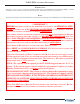
T5 PCI-EPP Conversion Procedures One Connector for Function Keys Field Replaceable Battery (see Caution below) *** CAUTION *** You must not remove battery from EPP without FIRST connecting a new battery! This EPP will be permanently damaged if unpowered and battery is removed before connecting a new battery! RL(2000/5000) / FT5000 PCI Conversion Left side Function keys Right side Left side Model RL (2000/5000) Function keys Right side Model FT5000 ** IMPORTANT ** The Function Key Cable has conn
T5 PCI-EPP Conversion Procedures TOOLS REQUIRED Phillips Screwdriver (Magnetic) RL/FT T5 PCI-EPP UPGRADE KITS (Models RL5XXX / FT5XXX / RL2XXX) 06200-08134 (UK) 06200-08138 (CAN) 06200-08136 (US) 06200-08142 (NETH) PARTS SUPPLIED PART NUMBER DESCRIPTION QUANTITY 1 03016-20XXX Keypad, PCI-EPP (Encrypting PIN Pad) 1 09120-07070 Dewhurst SPED Cable (Function Keys) 1 02054-00176 Screw, K40x20, PT Fastener 6 05200-10033 RL/FT/RT Software CD (includes kit #’s, install guides, software) 1 1 Count
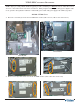
T5 PCI-EPP Conversion Procedures NOTE: Before proceeding with the hardware upgrade procedures, terminal power MUST be removed. Enter Management Functions > System Parameters > Shut Down the Terminal. When prompted “It is now safe to turn off your computer”on the screen, open the control panel/rear cabinet door and turn the power switch on the power supply to the (0) position. RL5000 / FT5000 Units: 1.
T5 PCI-EPP Conversion Procedures 3. Remove the VEPP SPED assembly and install the T5 PCI-EPP. secure with the six (6) screws included in kit (K40x20, PT Fastener Screw). Note: If there was a ground wire attached to the FT SPED, reattach and secure. ** IMPORTANT ** The K40x20 PT Fastener (included in the kit) should always be used to secure PCI-EPP’s with ground wire connections! Gnd wire connection Model RL5000 4. Model FT5000 Trace the two Function Key cables and disconnect/remove from the unit.
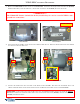
T5 PCI-EPP Conversion Procedures 5. Plug the combined, single connector for the Function keys (including the heater power cable if a Metal T5 PCIEPP w/heater is being installed) into the T5 PCI-EPP. Reconnect the SPED Data Cable previously removed (RJ-45 connector end). METAL T5 PCI-EPP W/HEATER CONVERSIONS ONLY! Properly dress and route the individual 12vdc heater cable through the cable guides, above and to the right of the EPP module.
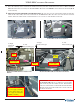
T5 PCI-EPP Conversion Procedures RL2000 Units NOTE: Before proceeding with the hardware upgrade procedures, terminal power MUST be removed. Enter Management Functions > System Parameters > Shut Down the Terminal. When prompted “It is now safe to turn off your computer”on the screen, open the control panel and turn the power switch on the power supply to the (0) position. 1. Disconnect the three (3) cables from the VEPP SPED assembly (2 Function key, 1 Data cable shown below).
T5 PCI-EPP Conversion Procedures 8” Display Function Key Cables (Remove/Replace): The figures below provide a basic view of where the function keys are in relation to the display case. 8” Display Assembly. Lift Green handle tab on X2 Main board and slide assembly back. Remove X2 Main Board from the Docking Board bracket. The ‘Right’ side function key cable can be accessed in the area shown in Figure below right. Disconnect the “Right” side function key cable shown .
T5 PCI-EPP Conversion Procedures Connect the new Function key cable ends to their respective keypad PCBs. The cable ends are marked “Left” and “Right”. Route split cable ends through the cable guides previously used for replaced cables. REMEMBER: Cable designations for the Function keys are referenced when viewing unit from the FRONT. Reference placement of connectors when viewing unit with control panel down (RL2000). View Figure below.
T5 PCI-EPP Conversion Procedures 5.7” Display Function Key Cables (Remove/Replace): The figures below provide a basic view of where the function keys are in relation to the display case. Left Right 5.7” Display Assembly. Lift Green handle tab on X2 Main board and slide assembly back. Remove X2 Main Board from the Docking Board bracket.
T5 PCI-EPP Conversion Procedures Remove screws from the Display assembly - Using the figure at lower right as a guide, remove the four (4) phillips-head screws from the display assembly. The figure below left shows the access hole locations on the display bracket. “Gently” lift the Display assembly up to get access to the Function key cables. Disconnect and remove these cables from the Control panel. Note: You may have to cut some Ty wraps to remove.
T5 PCI-EPP Conversion Procedures Lifting the Display assembly again, connect the new Function key cable ends to their respective keypad PCBs. The cable ends are marked replaced cables. “Left” and “Right”. Route split cable ends through the cable guides previously used for REMEMBER: Cable designations for the Function keys are referenced when viewing unit from the FRONT. Reference placement of connectors when viewing unit with control panel down (RL2000). View Figure below.
T5 PCI-EPP Conversion Procedures RT2000 PCI Conversion Model RT2000 Function keys Left side Right side ** IMPORTANT ** The Function Key Cable has connectors designated “LEFT” and “RIGHT”. This refers to the function keys and designations shown in the figure above. When installing this cable included in kit, REMEMBER the designations are referenced when viewed from FRONT of unit!.
T5 PCI-EPP Conversion Procedures TOOLS REQUIRED Phillips Screwdriver (Magnetic) RT T5 PCI-EPP UPGRADE KIT (Model RT2XXX) 06200-08135 (UK) 06200-08137 (US) 06200-08139 (CAN) 06200-08143 (NETH) PARTS SUPPLIED PART NUMBER DESCRIPTION QUANTITY 1 03016-20XXX Keypad, PCI-EPP (Encrypting PIN Pad) 1 09120-07070 Dewhurst SPED Cable (Function Keys) 1 3011-05219 SPED Mounting Bracket 1 05200-10033 RL/FT/RT Software CD (includes kit #’s, install guides, software) 1 1 Country specified RT Metal T5 PCI-EP
T5 PCI-EPP Conversion Procedures NOTE: Before proceeding with the hardware upgrade procedures, terminal power MUST be removed. Enter Management Functions > System Parameters > Shut Down the Terminal. When prompted “It is now safe to turn off your computer”on the screen, open the rear cabinet door and turn the power switch on the power supply to the (0) position. RT2000 Unit: 1. Open the vault door and slide the dispenser out. On the Control panel, disconnect the two (2) Function key cables.
T5 PCI-EPP Conversion Procedures 4. Place EPP assembly on a flat surface. Remove and retain the six (6) screws and nuts that secure the EPP to Remove and retain the cable guide. The T5 PCI-EPP requires a new SPED mounting bracket (included in the kit). 5. Mount the new SPED bracket to the T5 PCI-EPP as shown below. secure with the original six (6) screws and nuts previously removed. Remember to reinstall the cable guide on the new SPED mounting Bracket the the mounting bracket.
T5 PCI-EPP Conversion Procedures Battery Replacement Procedures 20
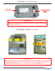
T5 PCI-EPP Conversion Procedures ** WARNING ** You must not remove battery from EPP without FIRST connecting a new battery! This EPP will be permanently damaged if unpowered and battery is removed before connecting a new battery! Battery Case Spare battery connection EXISTING BATTERY - DO NOT REMOVE BEFORE CONNECTING A SPARE BATTERY FIRST! 21
APPENDIX A
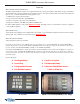
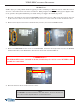
T5 PCI-EPP C ONVERSION P ROCEDURES UPDATING TERMINAL SOFTWARE (RL/FT5000/RL/RT2000) This step procedure describes how to perform a software update for the RL/FT5000/RL/ RT2000. You will need a Flash drive device (USB storage device shown) with the terminal software loaded in it (CD included in kits have software files specific for model ATM). * NOTE * To update software for Models FT5000 and RT2000, access Management Functions from the front display (customer side). 1.
APPENDIX A - LOADING SOFTWARE / KEY MANAGEMENT PROCEDURES 5. In the “LOOK IN” option should be the “USB” location. If it’s not present, out of the Software Update screen and then re-enter the same screen. 6. When the “LOOK I N” option has “USB” present, the “FILENAME ” screen should have the terminal software, size, and date/time attributes for each file loaded in the Flash drive. See NOTE, below.
T5 PCI-EPP C ONVERSION P ROCEDURES SAVE JOURNAL RECORDS DESCRIPTION: To view/save journal records, select the DISPLAY SELECTED RECORDS function. This allows you the option to specify if you want to save just “UNAUDITED” records, “AUDITED” or “both (ALL)”. You may also select the “type” of journal records to save (All, transaction, text record, cassette close, day close, or parameter change).
APPENDIX A - LOADING SOFTWARE / KEY MANAGEMENT PROCEDURES The report is displayed in a management report dialog that can be printed to the receipt printer or saved to an external memory device. The DISPLAY SELECTED RECORDS options save Journal files in a text (.txt) format. They can be viewed by a text editor. Press <6> to “SAVE TO FILE”.
T5 PCI-EPP C ONVERSION P ROCEDURES SAVE / RESTORE PARAMETERS USING AN EXTERNAL STORAGE DESCRIPTION: Use the “Save Parameters to an External Device” function to save the current terminal parameters to an external storage device that is attached to a USB port. Should it ever become necessary to restore the parameters, the “Restore Parameters From External Device” function can be used to quickly configure the terminal with the saved parameters.
APPENDIX A - LOADING SOFTWARE / KEY MANAGEMENT PROCEDURES The saved parameters will be loaded on the terminal. At the confirmation dialog, remove the jumpdrive. NOTE: When importing parameters, the user may be warned that the screen file versions have changed. Here is a sample warning screen: The user should press for each warning screen and . Verify all parameter settings are correct after the restore is complete.
T5 PCI-EPP C ONVERSION P ROCEDURES CLEAR SERIAL # ERROR After installing the T5 PCI-EPP, you will get a “Serial # Error”. In this event (and you must clear this error before entering keys in Key Management), option <4> will be an available option (active). Select this option to clear the error. The option will revert to “Grayed” out if the error hass been cleared. ACCESS INSTRUCTIONS: 1. From the MAIN M ENU screen, select DIAGNOSTICS by pressing <2> on the keypad. 2.
APPENDIX A - LOADING SOFTWARE / KEY MANAGEMENT PROCEDURES PCI-EPP (T5) / K EY M ANAGEMENT P ROCEDURES DIFFERENCES WITH THE T5 PCI-EPP KEYPAD USER PASSWORDS MUST BE AT LEAST 8 CHARACTERS, RATHER THAN 6. EPP WILL PROMPT WITH ERROR IF FEWER CHARACTERS ENTERED AND THEN TAKE YOU BACK TO PASSWORD ENTRY AT POINT YOU LEFT OFF. THERE IS NO WAY TO CLEAR THE PASSWORD. HIT AND START OVER. NO OR ON KEY ENTRY.
T5 PCI-EPP C ONVERSION P ROCEDURES ENTER MANAGEMENT FUNCTIONS > MAIN MENU > KEY MANAGEMENT. NOTE: PREVIOUSLY , USERS HAD TO ENTER THE INITIAL PASSWORD OF SIX (6) “Z EROS” BEFORE BEING ALLOWED TO SET THE PASSWORDS. THIS IS NO LONGER REQUIRED. SELECT “S ET U SER 1 PASSWORD” OPTION. ENTER NEW PASSWORD FOR USER 1. PASSWORDS CAN BE ANYWHERE FROM ‘8’ TO ‘16’ DECIMAL DIGITS. PRESS . YOU WILL BE PROMPTED AGAIN TO CONFIRM THE NEW PASSWORD . R E - ENTER NEW PASSWORD . PRESS .
APPENDIX A - LOADING SOFTWARE / KEY MANAGEMENT PROCEDURES SELECT “ENTER MASTER KEYS” OPTION. USER 1 ENTERS THE FIRST KEY PART (32 CHARACTERS). REFERENCE THE KEY LAYOUT DISPLAY BELOW. THE MAIN KEYPAD WILL MIRROR THE NUMBER/ALPHA NUMERIC KEYS. AFTER ENTERING THE KEYS, PRESS THE OPTION ON THE RIGHT-SIDE FUNCTION KEY . IMPORTANT: T HE REST OF THE PROCEDURES MUST BE COMPLETED WITHIN A 10 MINUTE PERIOD.
T5 PCI-EPP C ONVERSION P ROCEDURES 11 THE “CHECK DIGITS” PROMPT APPEARS. PRESS . A PROMPT APPEARS TO ENTER THE SECOND KEY PART. PRESS . USER 2 ENTERS THE SECOND KEY PART (32 CHARACTERS). REFER TO STEP 8 FOR ENTERING KEYS. THE “CHECK DIGITS” PROMPT APPEARS. YOU WILL BE PROMPTED THAT THE KEY WAS SUCCESS FULLY CHANGED. REPEAT SEQUENCE FOR ENTERING MAC MASTER KEY , IF REQUIRED.
APPENDIX A - LOADING SOFTWARE / KEY MANAGEMENT PROCEDURES CHECK OPERATION OF PRINTER/PRESENTER 1. Enter MANAGEMENT FUNCTIONS > MAIN MENU screen. Select DIAGNOSTICS option <2> , then PRINTER option <6>. 2. Press <1>, DEVICE STATUS. A Management report is displayed. 3. Scroll down to the “PRESENTER INSTALLED” and “PRESENTER STORED” line items. If there is a difference in the status report between either (ex: “Presenter Installed”: YES , “Presenter Stored”: NO), proceed to the next step. 4.
T5 PCI-EPP C ONVERSION P ROCEDURES OPTIONAL SCREENS / SCREEN BUTTONS The OPTIONAL SCREENS option in MANAGEMENT FUNCTIONS > TERMINAL CONFIGURATION will enable the user to configure the optional features as desired. The example of the Optional Screens dialog below includes all of the optional features. Important: There are NO country-specific options in the Optional Screens dialog: all options apply equally to all countries targeted by the combined screen file.