
Owner Manual

LIGHTED HIGHTOPPER - FIELD INSTALLATION GUIDE
4
AC
outlets
DC
outlets
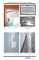
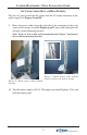
Figure 5a. Model 97XX.
AC
outlets
DC
outlets
Figure 5b. Model RL5000 (X-Scale).
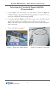
Figure 5c. Model RL5000 (XP)
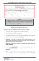
8. Connect the topper power cord. Ensure the ATM power is turned OFF
before connecting!
DC CONNECTIONS (LED-LIT TOPPER)
Plug the DC power cord (molex connector) from the topper into any available DC
output connector on the power supply (*see Notes) as shown in Figures 5a-5c.
1
Note: The dispensing mechanism uses the largest molex connection on the
power supply.
2
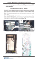
Note: Model RL5000XP only. The DC power cord may be an 8-pin or 2-pin
molex connector. The 8-pin connects to the power supply (Figure 5c) and the
2-pin connects to the GPIO board assembly (Figure 5d).
Figure 5d. Model
RL5000 (XP)
GPIO assy