
Owner Manual

LIGHTED HIGHTOPPER - FIELD INSTALLATION GUIDE
3
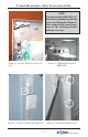
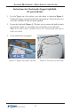
Figure 3. Screws started, not tightened.
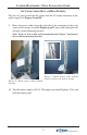
Figure 1. Corner bracket screw loca-
tion.
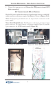
Figure 2. USB modem bracket
(RL5000).
Figure 4. Slotted mounting holes.
NOTE
Current production RL5000’s (X-
Scale) have a mounting bracket that
secures the USB modem (Figure 2).
After removal of the corner panels,
resecure the mounting bracket
with these 2 screws.