MODEL RL5000XP PC-based ATM INSTALLATION GUIDE VERSION 1.0 TDN 07102-00058 Oct 31 2008 Corporate Headquarters: tion) 522 E. Railroad Street Long Beach, MS 39560 Phone: (228) 868-1317 Fax: (228) 868-0437 RMA (Return Material AuthorizaReturn Address: 21405 Avenue “B” Long Beach, MS 39560 COPYRIGHT NOTICE © 2006 Delaware Capital Formation, Inc. All Rights Reserved.
RL5000XP Installation Guide What’s in this Installation Guide This Installation Guide gives step-by-step procedures for completing the physical installation of a Triton RL5000XP. This guide covers cabinet and dispenser installation (if applicable) for RL5000XP units equipped with an NMD-100 dispensing mechanism. The Installation Guide is divided into the following sections: Compliance Notifications. ATM Installation for Accessibility.
RL5000XP Installation Guide Disclaimer The manufacturer of the Automated Teller Machine (ATM) product(s) described herein makes no representations or warranties, either expressed or implied, by or with respect to anything in this manual, and shall not be liable for any implied warranties of fitness for a particular purpose or for any indirect, special, or consequential damages.
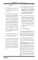
RL5000XP Installation Guide Harm to the Network: If the RL5000XP ATM causes harm to the telephone network, the telephone company will notify the customer that a temporary discontinuous of service may be required. If advanced notice is not possible, the telephone company will notify the customer as soon as possible. You will be advised of your right to file a complaint with the FCC if you believe it’s necessary.
RL5000XP Installation Guide Before installing this equipment, users should ensure that it is permissible to be connected to the facilities of the local telecommunications company. The equipment must also be installed using an acceptable method of connection. The customer should be aware that compliance with the above conditions may not prevent degradation of service in some situations. Repairs to certified equipment should be coordinated by a representative designated by the supplier.
RL5000XP Installation Guide Pour sa propre protection, l’utilisateur doit s’assurer que tous les fils de mise à la terre de la source d’énergie électrique, des lignes téléphoniques et des canalisations d’eau métalliques, s’fl y en a, sont raccordés ensemble. Cette précaution est particulièrement importante dans les régions rurales.
RL5000XP Installation Guide cause harmful interference in which case the user will be required to correct the interference at his own expense. Changes or modifications to this unit not expressly approved by the party responsible for compliance could void the user’s authority to operate the equipment.
RL5000XP Installation Guide This Page Intentionally Left Blank 8
ATM Installation for Accessibility 9
RL5000XP Installation Guide ATM Installation for Ac- 4.34 Automated Teller Machines. cessibility 1. This document supercedes all other information provided by Triton for ATM installation for accessibility. 2. Information provided in this manual is based on federal guidelines (ADA Accessibility Guidelines for Buildings and Facilities – ADAAG), as amended through January 1998. You should verify it has not been amended. States may also have accessibility codes.
ATM Installation for Accessibility (b) Reach Depth More Than 10 inches (255 mm).
RL5000XP Installation Guide 4.2.4 Clear Floor or Ground Space for Wheelchairs. 4.2.4.1 Size and Approach. The minimum clear floor or ground space required to accommodate a single, stationary wheelchair and occupant is 30 inches by 48 inches (760 mm by 1220 mm) (see Fig. 4a). The minimum clear floor or ground space for wheelchairs may be positioned for forward or parallel approach to an object (see Fig. 4b and 4c).
ATM Installation for Accessibility 4.2.6 Side Reach. If the clear floor space allows parallel approach by a person in a wheelchair, the maximum high side reach allowed shall be 54 inches (1370 mm) and the low side reach shall be no less than 9 inches (230 mm) above the floor (Fig. 6(a) and 6(b)). If the side reach is over an obstruction, the reach and clearances shall be as shown in Fig 6(c). Figures 4d. Clear floor space in alcoves. Figures 4e. Clear floor space in alcove.
RL5000XP Installation Guide Figure 5a. Forward reach, unobstructed. Figure 5b. Forward reach, obstructed. Figure 6a. Parallel approach - side reach. Figure 6b. Parallel approach - high/ low side reach.
ATM Installation for Accessibility Figure 6c. Side reach, obstructed. RL5000XP ADA requirements.
RL5000XP Installation Guide This Page Intentionally Left Blank 16
ATM Environmental Precautions Checklist 17
ATM Environmental Precautions Checklist When installing an ATM, some general environmental precautions need to be considered. Evaluate the location where the ATM will be installed. To help ensure proper operation of the ATM, ensure the environmental criteria listed in this checklist are met. TEMPERATURE/HUMIDITY 1. Dedicated source. The ATM AC power feed will be a dedicated line, to which no other electrical devices are connected.
Cabinet Dimensions 19
RL5000XP Installation Guide Service Area Dimensions Cabinet Dimensions (Side/Rear Views) [ 610 ] 24” Cable Feed Through 20
Cabinet Installation Standard Anchors 21
RL5000XP Installation Guide UL LEVEL 1 CABINET PARTS SUPPLIED 4 1/2" x 4 1/4 " Sleeve-Type Anchor Bolts 4 1/2" Flat Washers for Anchor Bolts 8 1/2" Nuts for Anchor Bolts 1 Drilling Template 4 Leveling Feet (for Optional Use with Business Hours Service Cabinets). 1 Torque Wrench, Adjustable to at least 60 Foot-Pounds (or 3/4" Ratchet Wrench). 1 Center Punch (or equivalent) for marking drilling points.
Cabinet Installation - Standard Anchors 5. Stand the unit up and walk it out of the shipping carton. 6. Remove the wrapping from the ATM. 7. Use the silver key to unlock both the control panel and the fascia door (which conceals the locking mechanism) on the front of the cabinet. Open the fascia door. 8. Turn the handle on the locking mechanism to open the front enclosure door. If the door is locked see the sidebar on this page for help in unlocking the electronic lock. 9.
RL5000XP Installation Guide 2. MARK/DRILL MOUNTING HOLES CONCRETE STRENGTH The floor at the installation location should consist of commercial-grade concrete measuring at least 2000 psi in compression strength. The full effectiveness of the mounting anchors depends upon meeting this specification! Check with the contractor/builder or owner of the installation to verify that this requirement can be satisfied. Mark the location of the cabinet mounting holes on the concrete floor.
Cabinet Installation - Standard Anchors LEVEL FLOORING REQUIREMENT It is very important that the ATM cabinet be located on flat, level flooring! If the floor is not flat and level the cabinet bottom and/or walls may become distorted when the mounting bolts are tightened down! This could prevent the security vault door from closing! BOLT CABINET TO FLOOR 1. Move the ATM into position for mounting by aligning the base over the four holes drilled in the previous procedure. 2.
RL5000XP Installation Guide 5. Ensure the cabinet is as level as possible given the floor conditions. Use a bubble level to verify this. If a bubble-level is not available, the cabinet can be “rocked” gently from front-toback and side-to-side to check the need for leveling. 6. Use a torque wrench and 3/4” socket to tighten each nut to a torque setting of 60 foot-pounds (required to establish the maximum pull-out strength of the anchors).
Cabinet Installation - Standard Anchors 10. The physical installation of the ATM cabinet is complete. Fig. 5. Tighten bolts with torque wrench. Fig. 6. Second nut installed. Fig. 7. Mounting hole drill template (Not to scale).
RL5000XP Installation Guide This Page Intentionally Left Blank 28
Cabinet Installation Chemical Anchors 21
RL5000XP Installation Guide UL LEVEL 1 CABINET **IMPORTANT** The following procedure applies to the OPTIONAL Chemical anchor install kit (06200-00060 - must purchase) SAFETY Level 1 cabinets are considerably heavier than Business Hours cabinets! Exercise extreme caution when moving Level 1 cabinets! At least two persons should work together to move the cabinet into position for mounting! PARTS SUPPLIED 4 Chemical Anchor capsules (02316-00002) 4 Threaded chisel-point rods, M12 x 1.
Cabinet Installation - Chemical Anchors 3. Remove the packing material from inside of the box. 4. Remove the silver key from the white plastic bag attached to the ATM wrapping. 5. Stand the unit up and walk it out of the shipping carton. 6. Remove the wrapping from the ATM. 7. Use the silver-colored key to unlock both the control panel and the fascia door (which conceals the locking mechanism) on the front of the cabinet. Open the fascia door. 8.
RL5000XP Installation Guide MARK/DRILL MOUNTING HOLES CHEMICAL ANCHOR SYSTEM Mark the location of the cabinet mounting holes on the concrete floor. This is accomplished as described below: 1. The chemical anchor installation system used in this procedure bonds threaded anchor-rod inserts to the base material (for ATM applications this is typically a concrete foundation).
Cabinet Installation - Chemical Anchors 3. 4. Use a 15 mm (9/16”) diameter carbide-tipped masonry bit to drill four holes at least 115 mm (4 1/2”) deep into the floor. Be sure to take into account the depth of any floor covering, such as tile or vinyl when gauging the depth of the anchor holes. Make sure the holes are drilled at least 115 mm (4 1/2”) into the concrete floor. Fig. 2. Blow out dust/debris.
RL5000XP Installation Guide INSTALL CHEMICAL ANCHORS 1. Move the ATM into position for mounting by aligning the base over the four holes drilled in the previous procedure. 2. Begin by inserting a chemical stud capsule into one of the mounting holes. Either end of the capsule may be inserted first. 3. Place a washer and a nut (in that order) onto a chisel point rod. Thread the nut onto the rod leaving 3 to 4 threads exposed. 4.
Cabinet Installation - Chemical Anchors 8. Repeat steps 1-7 for each of the remaining mounting holes. 9. Allow the adhesive to cure for the specified time (see chart below) prior to applying any load to the anchors. During the winter, the hole temperature may be different than the room temperature! The hole temperature should be measured to determine the curing time required. DO NOT disturb or load the anchors until they are fully cured! Fig. 7. Allow seated anchor to cure.
RL5000XP Installation Guide 2. 3. Use an adjustable crescent or ratchet wrench with 18 mm (3/4”) socket to tighten the nuts down. No minimum torque setting for the nuts is required. Simply ensure the nuts are tightened down firmly enough to secure the ATM cabinet to the anchors. Tightening the nuts just beyond hand tight should prove adequate. Fig. 8. Tighten nuts with wrench. Once all anchors are tightened, close the door of the cabinet to ensure that the door does not bind.
Cabinet Installation - Chemical Anchors Fig. 10. Mounting hole drill template (Not to scale).
RL5000XP Installation Guide This Page Intentionally Left Blank 38
Power and Communication 39
RL5000XP Installation Guide Connecting AC Power and Ethernet Cable ***WARNING*** This unit may be equipped with more than one power cord. Disconnect All Power Cords prior to Servicing! For continued fault protection, follow the correct voltage and current ratings when replacing any fuses. IMPORTANT: AC power for the terminal should come from a dedicated source with an isolated ground. 1. Ensure the power and Ethernet (CAT-5) cables are routed through the cable clips as shown in Figure 1. 2.
Power and Communication * IMPORTANT * Power Outlet Accessibility Whether you are installing a new outlet, or plan to use an existing outlet to supply power to the ATM, make sure the following requirements are met: Figure 2b. Power and phone cords routed through side access hole. 1. The outlet is located near the cabinet. 2. The outlet is easily accessible. 3.
RL5000XP Installation Guide This Page Intentionally Left Blank 42
NMD-100 Dispensing Mechanism Removal/Installation 43
RL5000XP Installation Guide Removing/Installing the NMD-100 Dispensing Mechanism The dispensing mechanism for the RL5000XP unit is shipped mounted on the slide rails inside the security vault. Several protective foam packs have been strategically placed behind and along each side of the dispensing mechanism to reduce any movement during transit. The foam packs must be removed before the dispensing mechanism can be extended out. Follow the procedures below for removal. 1. 2. Figure 1.
NMD-100 Dispensing Mechanism Removal/Installation Shutter cable Serial cable AC power cable On/Off switch Figure 4. Remove shutter and serial cables (left side of dispenser). Figure 5. Remove AC power cable. Figure 6. Remove shutter cable from clip. Figure 7. Remove power and data cable from clips. 7. Using two persons, grasp the green handles and lift the dispenser off the rails and slide out of the cabinet.
RL5000XP Installation Guide Reinstalling the NMD-100 Rail slots **CAUTION** Be certain that you have not applied power to the ATM before you continue! 1. 2. Refer to Figure 1. Pull the slide rails out of the cabinet until they reach their fully extended position. The right slide rail has a locking pin that must be disengaged to extend the rail. Ensure all cables have been moved out of the way so they will not be damaged while installing the dispensing mechanism in the cabinet. Figure 1.
NMD-100 Dispensing Mechanism Removal/Installation 4. Refer to Figure 4. Connect the serial communication data cable and the shutter cable to the connectors on the left side of the dispenser. For the serial data cable, use the forward -most connector as shown. The plug is keyed to ensure proper installation. 5. Connect the AC power cable to the dispenser power supply (Figure 5). Route the shutter, data, and power cables through the cable clips. 6.
RL5000XP Installation Guide This Page Intentionally Left Blank 48