TDM-100/150 TO NMD-50 CONVERSION PROCEDURES RL5000 TDN 07102-00062 March 17, 2014 Corporate Headquarters 21405 B Street Long Beach, MS. 39560 Phone: (800) 259-6672 Fax: (228) 868-9445 COPYRIGHT NOTICE © 2014 Triton. All Rights Reserved.
Document Updates March 2005 March 2014 Original Corrections to part numbers.
PURPOSE This guide covers the steps for replacing your TDM-100 or TDM-150 dispenser in the Model RL5000 ATM with an NMD50 multi-cassette dispenser. This procedure includes a list of all tools and hardware necessary for the conversion as well as the steps involved. SCOPE This procedure applies to all service personnel involved in the process of maintaining or converting Triton ATMs. APPLICATION The two (2) conversion kits available depend on the Model RL5000 unit cabinet you currently have.
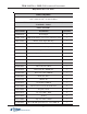
TDM-100/150 TO NMD-50 CONVERSION PROCEDURES REQUIRED PARTS AND TOOLS TOOLS REQUIRED Slotted and Phillips Screwdriver 11/32" (9mm) and 7/16" (11 mm) Nut Driver TDM to NM D-50 CONVERSION KIT (P/N 06200-00104) "T-Handle " Cabine t PARTS SUPPLIED PART NUM BER DESCRIPTION QUANTITY 0 9 2 0 0 - 0 12 15 Power Supply 1 0 9 0 0 5 - 0 3 15 0 NMD- 50 Mechanism (w/2 Cassettes and Reject Vault) 1 03011- 02033 Bracket, L- shaped, Slide Stop 1 02054- 00235 Screw, 4mm x 10mm, Low Profile, Slotted Panhead 6 03
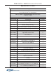
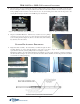
DISASSEMBLY PROCEDURES Before proceeding, follow these steps to remove power from the ATM: Enter Management Functions > System Parameters > Shut Down the Terminal. When prompted, turn power OFF on the ATMs power supply. Unlock and open the ATM control panel. Turn the power switch to the OFF (0) position. If possible, unplug the ATM power cord at the wall outlet. 1. Power Supply - Open the control panel. Disconnect all cables (AC/DC) from the terminal power supply (Figure 1).
TDM-100/150 TO NMD-50 CONVERSION PROCEDURES 4. Disconnect the power and communication (Comms) cables from the dispenser (Figure 9). Carefully cut any Ty wraps that are securing the cables to the dispenser. Remove the cables from the cabinet. Remove the note and reject cassettes. Using a phillips-head screwdriver, remove the four (4) or six (6) mounting screws that secure the dispenser to the swivel platform (Figure 10). Remove the TDM dispenser mechanism. Ferrite Figure 9.
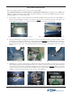
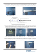
2. Left Side Slide Rail - Mount the other slide rail to the left cabinet bracket (Figure 5) using four (4) Truss phillip head screws (Figure 6). Use the diagram below for screw locations. Note: When installing slide rail, ensure the power/ phone cables are “tucked” behind the cabinet bracket as shown in Figure 5. Slide rails will be offset when extended. Figure 6. Slide rail installed. Figure 5. Cabinet bracket. 3.
TDM-100/150 TO NMD-50 CONVERSION PROCEDURES 5. Dispenser Power and Data Cables - Feed the EJ to Docking board cable (RJ-45 connector end) through the control panel access hole shown in Figure 12. Feed the dispenser power cable (insert) also up to the control panel (10-pin connector end). These 2 cables will be connected in later steps. Route the 2 cables in the vault area (EJ to dispenser, dispenser power cable end) in the existing cabinet cable clips (Figure 13). Dispenser power cable Figure 13.
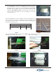
7. Power Supply/Cables - Open the control panel. Connect the EJ to Docking board cable (RJ-45 connector end) to the “Dispenser” port of Docking board. Route the cable through the cable guides (see Figure 4, “Disassembly Procedures”). Next, install the new power supply by reversing the procedures in Step 1, “Disassembly Procedures”. Reconnect all power cables (AC/ DC) to the power supply (Figure 19). Reconnect ATM power cord to wall outlet, if applicable. Figure 19. Power supply connected.
TDM-100/150 TO NMD-50 CONVERSION PROCEDURES REQUIRED PARTS AND TOOLS TOOLS REQUIRED Slotted and Phillips Screwdrivers 11/32" (9mm) and 7/16" (11 mm) Nut Driver TDM to NM D-50 CONVERSION KIT (P/N 06200-00103) "Lift Handle " Cabine t PARTS SUPPLIED PART NUM BER DESCRIPTION QUANTITY 09200- 01215 Power Supply 1 09005- 13150 NMD- 50 Mechanism (w/2 Cassettes and Reject Vault) 1 03011- 02033 Bracket, Acute Angle, Slide Stop 1 02054- 00320 8- 32 x 3/8 Phil Truss HD Machine Screw 1 03011- 00760 Handl
DISASSEMBLY PROCEDURES Before proceeding, follow these steps to remove power from the ATM: Enter Management Functions > System Parameters > Shut Down the Terminal. When prompted, turn power OFF on the ATMs power supply. Unlock and open the ATM control panel. Turn the power switch to the OFF (0) position. If possible, unplug the ATM power cord at the wall outlet. 1. Power Supply - Open the control panel. Disconnect all cables (AC/DC) from the terminal power supply (Figure 1).
TDM-100/150 TO NMD-50 CONVERSION PROCEDURES 4. Disconnect the power and communication (Comms) cables from the dispenser (Figure 9). Carefully cut any Ty wraps that are securing the cables to the dispenser. Remove the cables from the cabinet. Remove the note and reject cassettes. Using a phillips-head screwdriver, remove the four (4) or six (6) mounting screws that secure the dispenser to the swivel platform (Figure 10). Remove the TDM dispenser mechanism. Ferrite Figure 9.
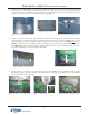
UPGRADE KIT ASSEMBLY PROCEDURES 1. Electronic Journal (EJ) and Bracket - The EJ (yellow), bracket, and cables (2 - EJ to dispenser, EJ to docking board) should be pre-assembled in the kit. If they are not, use Figure 1 as a reference for assembly. Locate the two (2) bolts in the upper right, rear of the vault area (Figure 2). Mount the EJ assembly to the bolts (cable connects towards top of cabinet, Figure 3) and secure with the two (2) Kep nuts provided using a 7/16" nut driver. Figure 1.
TDM-100/150 TO NMD-50 CONVERSION PROCEDURES 4. Dispenser/Cabinet Grounds - Reconnect the cabinet ground wire removed in Step 7 (page 11) to the front left screw. Install the dispenser ground wire included and secure both ground wires with the nut previously removed (Figure 9). The other end of dispenser ground wire will attach to the NMD-50 when installed. 5. Dispenser Power and Data Cables - Feed the EJ to Docking board cable (RJ45 connector end) through the control panel access hole.
8. Power Supply/Cables - Open the control panel. Connect the EJ to Docking board cable (RJ-45 connector end) to the “Dispenser” port of Docking board. Route the cable through the cable guides (see Figure 4, “Disassembly Procedures”). Next, install the new power supply by reversing the procedures in Step 1, “Disassembly Procedures”. Reconnect all power cables (AC/ DC) to the power supply (Figure 17). Reconnect ATM power cord to wall outlet, if applicable. Figure 17. Power supply connected.