
Owner Manual


3
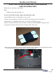
7. Remove the paper backing from the four double sided tape squares. With the Power and Serial Ports facing
towards the docking board, stick the modem to the main board bracket.
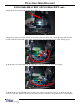
FOR UNITS WITH NO BRACKET, 03011-01606 OR
03011-01036 BRACKET
The Modem is located in the control panel.
Tools:
1 - ESD wrist strap with grounding cord.
To remove the modem assembly complete the following procedure:
1. Put the ESD wrist strap on and attach the cord to ground.
2. Perform a proper shutdown of the unit. Unlock and open the upper portion of the cabinet.
3. Push the AC power ON/OFF switch on the power supply to the OFF (0) position.
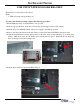
4. Remove the current modem from the unit. Remove all modem cables EXCEPT for the phone cable.
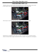
5. Apply the four double sided tape squares to the back of the serial modem.