XSCALE TRITON SERIAL MODEM FIELD REPLACEMENT PROCEDURE RL5XXX, FT5XXX & RT2XXX TDN 07103-00351 JUNE 5, 2014 CORPORATE HEADQUARTERS: 21405 B Street Long Beach, MS 39560 Phone: (228) 575-3100 Fax: (228) 575-3101 COPYRIGHT NOTICE © 2014 Triton. All Rights Reserved.
XSCALE SERIAL MODEM REPLACEMENT TABLE OF CONTENTS SECTION 1 ..........................................................................................................................................................1 REQUIRED TOOLS AND PARTS SUPPLIED........................................................................................2 UNITS WITH NO BRACKET, 03011-01606 OR 03011-01036 BRACKET...........................................3 UNITS WITH 03011-01810 BRACKET........................................
TOOLS REQUIRED ESD wrist strap with grounding cord KIT P/N: 06200-00351 Serial POTS Modem 1 Security Module Power Cable 1 Security Module Communication Cable 1 Double Sided Tape 1” x 1” x .062” 4 After installing the software to enable the serial modem (xt20xtsm1.0.0.
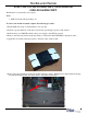
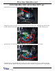
FOR UNITS WITH NO BRACKET, 03011-01606 OR 03011-01036 BRACKET The Modem is located in the control panel. Tools: 1 - ESD wrist strap with grounding cord. To remove the modem assembly complete the following procedure: 1. Put the ESD wrist strap on and attach the cord to ground. 2. Perform a proper shutdown of the unit. Unlock and open the upper portion of the cabinet. 3. Push the AC power ON/OFF switch on the power supply to the OFF (0) position. 4. Remove the current modem from the unit.
03011-01606 BRACKET OR NO BRACKET cont... 8. Plug the phone cable into the modem “Line In” port. 9. Plug the modem power cable and the modem data cable into the modem. Route the data cable from the modem, under and around the other cables, and plug it into the “Auxiliary” port on the docking board. 10. Route the power cable under all the other cables and plug it into the unit power supply. 11. Push the AC power ON/OFF switch on the power supply to the ON (I) position.
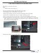
FOR UNITS WITH 03011-01810 BRACKET The Modem is located in the control panel. Tools: 1 - ESD wrist strap with grounding cord. To remove the modem assembly complete the following procedure: 1. Put the ESD wrist strap on and attach the cord to ground. 2. Perform a proper shutdown of the unit. Unlock and open the upper portion of the cabinet. 3. Push the AC power ON/OFF switch on the power supply to the OFF (0) position. 4. Remove the current modem from the unit.
03011-01810 BRACKET cont... 7. Plug the modem power cable and the modem data cable into the modem. Route the data cable from the modem, under the other cables, and plug it into the “Auxiliary” port on the docking board. 8. Route the power cable under all the other cables and plug it into the unit power supply. 9. Push the AC power ON/OFF switch on the power supply to the ON (I) position. Load the modem kit software to the unit.
SECTION 2 FT5000 & RT2000 KIT 06200-10009
XSCALE SERIAL MODEM REPLACEMENT ESD wrist strap with grounding cord #2 Phillips screwdriver #1 flathead screwdriver Side cutters TOOLS REQUIRED KIT P/N: 06200-10009 FIELD INSTALL KIT, SERIAL MODEM, XSCALE MODEL RT2XXX & FT5XXX DESCRIPTION QUANTITY Xscale Main Board 1 Serial POTS Modem 1 Edgeport USB to Serial Adapter, Spacers (2) & USB Cable 1 USB Modem Mounting Bracket 1 Modem Power Cable 1 Power Connector Splitter 1 Adapter Jack 1 Modem Communication Cable 1 12ft Phone Cable 1 Ve
FIELD REPLACEMENT PROCEDURE After installing the software to enable the serial modem, the modem settings in diagnostics will show the following: Modem / Ethernet Device ID: Triton Modem Host: Baud Rate: 57600 Byte Size: 8 Parity: None Stop Bits: 1 Modem Setup String: \N0&H6&G4 Triton Connect: Baud Rate: 57600 Byte Size: 8 Parity: None Stop Bits: 1 Modem Setup String: \V2&H0 NOTE: Before proceeding, swap out the unit’s main board with the supplied main board loaded with the updated software.
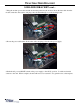
XSCALE SERIAL MODEM REPLACEMENT To Remove the Modem Assembly: 1. Put the ESD wrist strap on and attach the cord to ground. 2. Perform a proper shut down of the unit. 3. Perform a proper shutdown of the unit. Unlock and open the upper portion of the cabinet. 4. Push the AC power ON/OFF switch on the power supply to the OFF (0) position. 5. Remove the current modem from the unit. Remove all modem cables EXCEPT for the phone cable.
FIELD REPLACEMENT PROCEDURE To Install the Serial Modem Assembly: 1. Put the ESD wrist strap on and attach the cord to the ground. 2. Perform a proper shut down of the unit. 3. Unlock and open the upper portion of the cabinet. 4. Push the AC power ON/OFF switch on the power supply to the OFF (0) position. 5. Remove the screw in the middle at the top of the display bracket. (This screw may already be removed if the unit previously had a Multitech modem bracket installed).
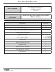
XSCALE SERIAL MODEM REPLACEMENT 7. Peel the paper backing off the two soft dots of Velcro. Adhere them to the USB to Serial Adapter as shown. Stick the two hard dots of Velcro to the soft dots. Once stuck together, remove the paper backing off the hard dots. 8. Adhere the Modem Assembly to the main board cover with the USB port facing down as shown. 9. Obtain the Serial Modem. Notice the two slots in the back of the modem.
FIELD REPLACEMENT PROCEDURE 10. Line the two posts on the bracket up with the two slots on the back of the modem. Slide the modem in towards the bracket until it snaps into place. 11. Plug the Phone Cable into the “Line In” port on the side of the modem. If the unit does not have a previously installed phone cable, use the Phone Cable supplied in the kit. 12. Plug the Modem Communication Cable into the “Serial” port on the side of the modem.
XSCALE SERIAL MODEM REPLACEMENT 13. Plug the Modem Power Cable into the “Power” port on the side of the modem. Route the Modem Power Cable around the back of the modem and down. 14. Plug the Modem Power Cable into the Power Connector Splitter Cable as shown below. 15. Plug the Power Connector Splitter Cable into the power supply. If there are no open ports, unplug a cable, plug it into the second jack on the power splitter cable and plug the splitter into the power supply.
FIELD REPLACEMENT PROCEDURE 16. Plug the USB Cable into the USB to Serial Adapter. Plug the other end of the USB Cable into a USB port on the docking board. 17. Fold the excess USB cable on itself to keep it from interferring with the unit’s moving parts. TY Wrap the cable in two places to secure it in place.
XSCALE SERIAL MODEM REPLACEMENT To Route the Phone Cable: 1. Route the phone cable down along the cabinet wall and through the large hole as shown. 2. Continue routing the phone cable through the smaller opening into the lower cabinet. Secure the cable in the cable clips along the back wall of the cabinet and then out of the unit.