
Owner Manual

7
SECTION 1 - CONVERSION WITH “OLDER” STYLE CABINETS (W/T-HANDLE)
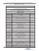
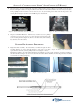
5. Dispenser Power and Data Cables - Feed the EJ to Docking board cable (RJ-45 connector end) through the control
panel access hole shown in Figure 12. Feed the dispenser power cable (insert) also up to the control panel (10-pin
connector end). These 2 cables will be connected in later steps. Route the 2 cables in the vault area (EJ to dispenser,
dispenser power cable end) in the existing cabinet cable clips (Figure 13).
Figure 12. EJ to Docking board cable.
Figure 13. Route power/data cables.
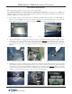
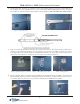
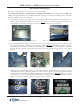
5. Dispenser - Extend the slides fully. Ensure all cables in vault area have been moved out of way before installing
mechanism. Remove cardboard support from mechanism cassettes. With 2-personnel, lift the NMD-50 by the green
handles and align the rails on the dispenser with the slide rails. Start inserting the rail on the RIGHT
first, then the
LEFT due to the offset of the rails (Figure 14). Slide mechanism up to the rail stops, then push the RIGHT release in,
then LEFT (Figure 15) and continue sliding mechanism fully into cabinet. Repeat extending/inserting mechanism
into cabinet a few times to ensure no binding on slide rails.
Figure 14. Rails extended (offset).
Figure 15. Push release tabs “in”.
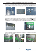
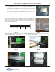
6. Dispenser Cables - Connect the power, data, and ground wires to the NMD-50 as shown in Figures 16 and 17. Route
the cables through the cable clips attached to the mechanism covers (Figure 18). Ground wire routes down behind
slide and through the lower cable clips.
Figure 16. Power cable connection. Figure 17. Data/ground connections.
Figure 18. Route cables thru clips.
Dispenser power cable
Release tab
Ground wire routing