
Owner Manual

6
TDM-100/150 TO NMD-50 CONVERSION PROCEDURES
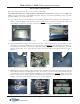
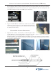
2. Left Side Slide Rail - Mount the other slide rail to the left cabinet bracket (Figure 5) using four (4) Truss phillip head
screws (Figure 6). Use the diagram below for screw locations. Note: When installing slide rail, ensure the power/
phone cables are “tucked” behind the cabinet bracket as shown in Figure 5. Slide rails will be offset when extended.
Figure 5. Cabinet bracket.
Figure 6. Slide rail installed.
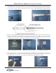
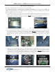
3. Electronic Journal (EJ) and Bracket - The EJ (yellow), bracket, and cables (2 - EJ to dispenser, EJ to docking board)
should be pre-assembled in the kit. If they are not, use Figure 7 as a reference for assembly. Locate the two (2) bolts
in the upper right of the vault area (Figure 8). Mount the EJ assembly to the bolts (cable connects towards rear of
cabinet) and secure with the two (2) Kep nuts provided using a 7/16" nut driver (Figure 9).
Figure 7. EJ and hardware assembly. Figure 8. Mounting bolt location. Figure 9. EJ mounted.
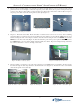
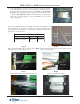
4. Dispenser Ground - Remove the cabinet ground bolt (Figure 10), if installed. If no bolt is available, one is included in
the kit. Install the dispenser ground wire included and secure both ground wires with the bolt previously removed or
one included (Figure 11). The other end of ground wire will attach to the NMD-50 when installed.
Figure 10. Remove door ground bolt. Figure 11. Dispenser ground installed.
Dispenser ground