SECURITY MODULE UPGRADE TRAVERSE TDN 07103-00232 February 27, 2014 Corporate Headquarters 21405 B Street Long Beach, MS 39560 Phone: (800) 259-6672 Fax: (228) 868-9445 COPYRIGHT NOTICE © 2014 Triton. All Rights Reserved.
ADVANCED SECURITY MODULE UPGRADE PROCEDURES Document Updates February 27, 2014 Original Ensure the most up-to-date software is installed on the unit BEFORE proceeding.
INTRODUCTION INTRODUCTION PURPOSE This guide covers the steps for installing a new Security Module (SM). The new module adds additional security to the mainboard to dispenser communications path. These procedures include a list of all tools and hardware necessary for the replacement as well as the steps involved. SCOPE These procedures apply to all VERIFIED TRITON TRAINED service personnel involved in the process of maintaining or converting Triton ATMs.
ADVANCED SECURITY MODULE UPGRADE PROCEDURES REQUIRED PARTS AND TOOLS TOOLS REQUIRED KIT 06200-00189 #2 Phillips screwdriver with a 4 inch shank Small flathead screwdriver with an 8 inch shank Side cut pliers USB flash drive Small paperclip (straightened out) Traverse with SCDU or HCDU - Advanced Security Module Upgrade Kit Part # 09105-80309 03011-02109 09120-07162 09120-00589 09120-00590 03072-00052 02054-00343 Description FT/RL/Traverse Live- (PPA) Security Module v2.
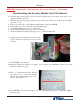
TRAVERSE Skip to page 6 and perform the security module installation and cable routing BEFORE completing the “Synchronizing the Security Module...” instructions. Synchronizing the Security Module to the Mainboard 1. Open the upper cabinet and power up the unit by flipping the power switch on the unit’s power supply to the ON position (I). 2. When the unit is powered up completely, press and hold the “blank” key on the keypad and then press the “1” key. 3.
ADVANCED SECURITY MODULE UPGRADE PROCEDURES TRAVERSE UPGRADE BEFORE PROCEEDING: • • • • Ensure all of your Journal Records have been saved to a USB flash drive. Perform a proper management function shut down to remove power from the ATM. Unlock and open the ATM control panel. Turn the power switch to the OFF (0) position. If possible, unplug the ATM power cord at the wall outlet. Open the dispenser area. Installation 1. Obtain the security module and bracket.
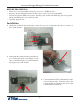
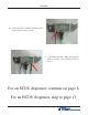
TRAVERSE 4. Connect the CDU to SM Power Splitter cable to the security module as shown. 5. Connect the Controller to SM Communication Extension cable to the security module as shown. For an SCDU dispenser, continue on page 8. For an HCDU dispenser, skip to page 13.
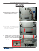
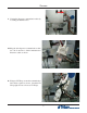
ADVANCED SECURITY MODULE UPGRADE PROCEDURES SCDU 6. Pull the dispenser out to the fullest extension. (picture of SCDU before any upgrades). 7. Locate the two screws on the bottom of the mainboard cover as shown. Remove the screws and set aside for reinstallation. 8. Install the security module bracket under the cover. Using the inner two screw holes, reinstall the two screws to secure the assembly and the cover as shown. Ensure the bracket is sitting flat against the dispenser.
TRAVERSE 9. Unplug the dispenser communication cable by loosening the thumbscrews. 10. Plug the unit dispenser communication cable into the Controller to SM Communication Extension cable as shown. 11. Using two TY Wraps, secure the communication data cables together as shown. Cinch the TY Wraps tight and cut off excess TY Wraps.
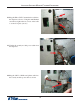
ADVANCED SECURITY MODULE UPGRADE PROCEDURES 12. Plug the SM to CDU Communication cable into the dispenser as shown. Using the small flathead screwdriver, tighten the two screws on the cable to secure it in place (arrows). 13. Unplug the security module power cable from the dispenser. 14. Plug the CDU to SM Power Splitter cable into the security module power cable as shown.
TRAVERSE 15. Plug the CDU to SM Power Splitter cable into the dispenser as shown. 16. Ensure the CDU to SM Power Splitter cable is routed BEHIND the SM to CDU Communication cable and IN FRONT of the Controller to SM Communication Extension cable as shown. 17. Remove the screw from the dispenser bracket and install a quick release cable clip using the same screw as shown. Angle the clip slightly for easier cable routing.
ADVANCED SECURITY MODULE UPGRADE PROCEDURES 18. Route all the cables through the cable clip as shown. 17. Fold all the cables against the dispenser as shown. TY Wrap them together where necessary to keep the cables against the dispenser. Cut off excess TY Wraps. Push the dispenser back into the unit and ensure the cables don’t hit the cabinet wall. 18. To complete the security module install, perform “Synchronizing the Security Module to the Mainboard” on page 3.
TRAVERSE HCDU (continued from page #7) 6. Pull the dispenser out to the fullest extension. (picture of HCDU before any upgrades). 7. Locate the two screws on the bottom of the mainboard cover as shown. Remove the screws and set aside for reinstallation. 8. Install the security module bracket under the cover. Using the outer two screw holes, reinstall the two screws to secure the assembly and the cover as shown. Ensure the bracket is sitting flat against the dispenser.
ADVANCED SECURITY MODULE UPGRADE PROCEDURES 9. Unplug the dispenser communication cable by loosening the thumbscrews. 10. Plug the unit dispenser communication cable into the Controller to SM Communication Extension cable as shown. 11. Using two TY Wraps, secure the two communication cables together as shown. Cinch the TY Wraps tight and cut off excess TY Wraps.
TRAVERSE 12. Plug the SM to CDU Communication cable into the dispenser as shown. Using the small flathead screwdriver, tighten the two screws on the cable to secure it in place (arrows). 13. Unplug the security module power cable from the dispenser. 14. Plug the CDu to SM Power Splitter cable into the security module power cable as shown.
ADVANCED SECURITY MODULE UPGRADE PROCEDURES 15. Plug the CDU to SM Power Splitter cable into the dispenser as shown. 16. Ensure the CDU to SM Power Splitter cable is routed BEHIND the SM to CDU Communication cable and IN FRONT of the Controller to SM Communication Extension cable as shown. 17. Install a quick release cable clip using the supplied screw as shown.
TRAVERSE 18. Route all the cables through the clip as shown. 19. Fold all the cables against the dispenser as shown. Pull the cables down away from the blue wheel (green arrow). TY Wrap the cables together where necessary to keep the cables against the dispenser. Cut off excess TY Wraps. Push the dispenser back into the unit and ensure the cables don’t hit the cabinet wall. 18. To complete the security module install, perform “Synchronizing the Security Module to the Mainboard” on page 3.