
Owner Manual


2-20
HOLE CLOSEOUT BRACKET KIT
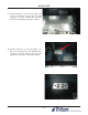
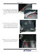
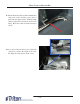
5. Route the security module power cable and the
security module communication cable through
the quick release cable clip and into the upper
cabinet through the back left opening and the
anti-phishing bracket as shown.
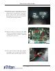
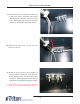
6. Obtain the dispenser power cable. Plug the
power cable into the unit’s power supply in the
upper portion of the cabinet. Route the cable
through the left hole opening into the lower
cabinet.
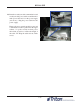
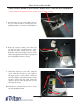
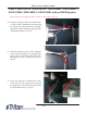
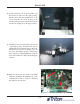
7. Route the dispenser communication cable
down in front of the dispenser tray, through
the quick release cable clip, under the tray and
up from behind the tray as shown.
Vault # 03015-00798 / 03015-00212 / 03015-00841 / 03015-00851 /
03015-01841 / 03015-00851 / 03015-01841 with an SDD Dispenser
**If the unit has been upgraded with a security module, skip to step #8.