CLOSE OUT PLATE KIT TDN 07103-08210 August 23, 2014 Corporate Headquarters 21405 B Street Long Beach, MS 39560 Phone: (800) 259-6672 Fax: (228) 575-3101 COPYRIGHT NOTICE © 2014 Triton. All Rights Reserved.
HOLE CLOSE OUT BRACKET KIT Document Updates August 23, 2014 Original Improper grounding may cause damage to ATM and/or components.
HOLE CLOSE OUT BRACKET KIT INTRODUCTION SCOPE SECTION 1 SECTION 2 SECTION 3 TABLE OF CONTENTS SHALLOW CABINET RL1600 MM RL5000 SDD RL5000 NMD50 3 3 1-1 2-1 3-1 INTRODUCTION This guide covers the steps for rerouting cables for the close out kits. For Shallow cabinets the close out kits are not needed but the cables need to be rerouted. SCOPE These procedures apply to all VERIFIED TRITON TRAINED service personnel involved in the process of maintaining or converting Triton ATMs.
SECTION 1 HOLE CLOSEOUT BRACKET KIT KIT 06200-08211 RL1600 AND RL2300 SHALLOW CABINET WITH MM
HOLE CLOSEOUT BRACKET KIT REQUIRED PARTS AND TOOLS TOOLS REQUIRED PART REQUIRED 03072-00009 USB flash drive Panduit Adhesive Cable Clip RL1600 and RL2300 with the following shallow cabinets with MiniMech does not need the hole closeout bracket kit. The cables do need to be reouted per this section.
RL1600 AND RL2300 SHALLOW CABINET WITH MM BEFORE PROCEEDING: • • • • Ensure all of your Journal Records have been saved to a USB device. Perform a proper management function shut down to remove power from the ATM. Unlock and open the ATM control panel. Turn the power switch to the OFF (0) position. If possible, unplug the ATM power cord at the wall outlet. Open the dispenser area. 1. Disconnect the dispenser communications and power cables from the dispenser.
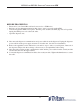
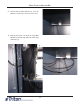
HOLE CLOSEOUT BRACKET KIT 5. Underneath the Mini Mech tray, add the Adhesive Cable Clip to the back, left corner. 6. Run the data cable over the front of the Mini Mech Tray, then through Adhesive Cable Clip under the tray.
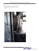
RL1600 AND RL2300 SHALLOW CABINET WITH MM 7. The data cable then comes back over the front of the Mini Mech tray and plugs into the Mini Mech.
SECTION 2 HOLE CLOSEOUT BRACKET KIT KIT 06200-08211 RL5000 CABINET OR VAULT SDD
HOLE CLOSEOUT BRACKET KIT REQUIRED PARTS AND TOOLS TOOLS REQUIRED USB flash drive 7/16” hollow shaft nut driver Possible additional tools required: - #2 Phillips screwdriver - Side cut pliers KIT 06200-08211 Hole Closeout Bracket Kit Description Closeout Bracket 1/4-20 Nylon Lock Hex Jam Nut 1/4-20 x 1.25 Steel Carriage Bolt Cable Clip|3/4" Round, Screw-In|Quick Release| ROHS Nut|#8-32|Hex Nut|Ext.
RL5000 SDD RL5000 UPGRADE **If the unit has been upgraded with the “Electronic Journal to Security Module Upgrade Kit”, skip to the table of contents on page 4 to locate the page number of the work instructions for the correct unit. BEFORE PROCEEDING: • • • • Ensure all of your Journal Records have been saved to a USB device. Perform a proper management function shut down to remove power from the ATM. Unlock and open the ATM control panel. Flip the switch on the power supply to the OFF (0) position.
HOLE CLOSEOUT BRACKET KIT Use the table of contents below to locate your unit’s serial number and page number of the correct installation and cable routing.
RL5000 SDD Cabinet # 09700-00000 with an SDD Dispenser **If the unit has been upgraded to security module, skip to step #8. 5. Feed the security module power cable and communication cable down through the left opening into the lower cabinet. Route the cables through the upper left front and upper back middle cable clips as shown. Plug the cables into the security module. 6. Obtain the dispenser power cable. Plug the power cable into the unit’s power supply in the upper portion of the cabinet.
HOLE CLOSEOUT BRACKET KIT 8. Install the 6 bolts into one closeout bracket. Set the closeout bracket in place into the right opening as shown. Ensure the bolts and bracket are sitting flat on the upper cabinet. 9. Ensure the bolts are not intertwined in the cables in the lower cabinet. 10. Install the second closeout bracket on the bolts in the lower cabinet. Using the 7/16” hollow shaft nut driver, install the 6 hex nuts on the bolts.
RL5000 SDD 11. Plug the cables into the back of the SDD dispenser and tighten the thumbscrews on the communication cable to secure it. Reinstall the dispenser into the unit. 12. Ensure all excess security module power cable and communication cable is pulled into the upper cabinet. Loop the security module power cable back on itself to condense the length of the cable. TY Wrap the cable and cut off the excess (blue box). TY Wrap the cables on the side of the power supply and cut off excess (green arrow).
HOLE CLOSEOUT BRACKET KIT Cabinet # 03015-00052 & 03015-00167 with an SDD Dispenser **If the unit has been upgraded with a security module, skip to step #8. 5. Feed the security module power cable and communications cable through the left front opening into the lower cabinet. Route the cables through the left cable clips as shown. Plug the cables into the security module. 6. Obtain the dispenser power cable. Plug the power cable into the unit’s power supply in the upper portion of the cabinet.
RL5000 SDD 8. Install the 6 bolts into one closeout bracket. Set the closeout bracket in place into the right opening. Install 6 more bolts into another closeout bracket. Set the second closeout bracket into the back opening as shown. Ensure the bolts and brackets are sitting flat on the upper cabinet. 9. Ensure the bolts are not intertwined in the cables in the lower cabinet. 10. Remove the cable clip in the rear left corner of the lower cabinet for easier installation of the closeout bracket.
HOLE CLOSEOUT BRACKET KIT 11. Install the lower close out bracket on the bolts. Using the 7/16” hollow shaft nut driver, install 6 hex nuts on the bolts. While tightening, ensure the bolts and bracket are sitting flat in the upper cabinet. 12. Reinstall the cable clip over the closeout bracket as shown. 13. Install the second lower closeout bracket on the bolts in the lower cabinet. Using the 7/16” hollow shaft nut driver, install the 6 hex nuts on the bolts.
RL5000 SDD 14. Plug the cables into the back of the SDD dispenser and tighten the thumbscrews on the communication cable to secure it. Reinstall the dispenser into the unit. 15. Ensure all excess security module power cable and communication cable is pulled into the upper cabinet. Loop the security module power cable back on itself to condense the length of the cable (blue box). TY Wrap the cable and cut off the excess. TY Wrap the cables on the side of the power supply and cut off excess (green arrow).
HOLE CLOSEOUT BRACKET KIT RL 5000 with Cabinet # 03015-00793 / 03015-00833 / 03015-01340 / 03015-00852 / 03015-00900 with an SDD Dispenser **If the unit has been upgraded with a security module, skip to step #8. 5. Feed the security module power cable and the communication cable through the front left opening into the lower cabinet. Route the cables through the quick release cable clip and plug them into the security module. 6. Obtain the dispenser power cable.
RL5000 SDD 8. Install 6 bolts into one closeout bracket. Set the closeout bracket in place into the right opening as shown. Ensure the bolts and bracket are sitting flat in the upper cabinet. 9. Install 4 bolts into one closeout bracket. Set the closeout bracket into the middle circle opening as shown. Ensure the bolts and bracket are sitting flat on the upper cabinet.
HOLE CLOSEOUT BRACKET KIT 10. Install the lower closeout bracket on the bolts in the lower cabinet. Using the 7/16” hollow shaft but driver, install the nuts on the bolts; 6 nuts on the nut and 4 bolts in the middle. While tightening, ensure the bolts and bracket are sitting flat in the upper cabinet. 11. Plug the cables into the back of the SDD dispenser and tighten the thumbscrews on the communication cable to secure it. Reinstall the dispenser into the unit. 12.
RL5000 SDD 13. Route the security module communication and security module power cable around the unit’s main power cable and over the power supply (red arrows). Plug the power cable into the power supply. Ensure all excess security module power and communication cable is pulled into the upper cabinet. Loop the security module power cable back on itself to condense the length of the cable. TY Wrap the cable and cut off the excess.
HOLE CLOSEOUT BRACKET KIT Vault # 03015-00064 / 03015-00200 / 03015-00227 with an SDD Dispenser **If the unit has been upgraded with a security module, skip to step #9. 5. From the upper portion of the cabinet, remove the two bolts & washers securing the antiphishing bracket. Set aside for reinstallation. 6. Route the security module power cable and security module communications cable through the upper middle back two clips.
RL5000 SDD 8. Loop the SDD dispenser communication cable back on itself twice to condense the length of the cable to match the length of the dispenser power cable. TY Wrap the two cables together in two spots as shown. Cut off the excess TY Wraps. 9. Install 6 bolts into one closeout bracket. Set the closeout bracket in place in the right opening. Install 6 bolts in the second closeout bracket. Set the second closeout bracket in the read left opening.
HOLE CLOSEOUT BRACKET KIT 11. Install the lower closeout bracket on the bolts in the lower cabinet. Using the 7/16” hollow shaft nut driver, install the 6 hex nuts on the bolts. While tightening, ensure the bolts and bracket are sitting flat in the upper cabinet. 12. Reinstall the cable clip over the closeout bracket as shown. 13. Install the second lower closeout bracket on the bolts in the lower cabinet. Using the 7/16” hollow shaft nut driver, install the 6 hex nuts on the bolts.
RL5000 SDD 14. Plug the cables into the back of the SDD dispenser and tighten the thumbscrews on the communication cable to secure it. Reinstall the dispenser into the unit. 15. Route the security module communication and security module power cable around the unit’s main power cable and over the power supply (red arrows). Plug the power cable into the power supply. Ensure all excess security module power and communication cable is pulled into the upper cabinet.
HOLE CLOSEOUT BRACKET KIT Vault # 03015-00798 / 03015-00212 / 03015-00841 / 03015-00851 / 03015-01841 / 03015-00851 / 03015-01841 with an SDD Dispenser **If the unit has been upgraded with a security module, skip to step #8. 5. Route the security module power cable and the security module communication cable through the quick release cable clip and into the upper cabinet through the back left opening and the anti-phishing bracket as shown. 6. Obtain the dispenser power cable.
RL5000 SDD 8. Install 6 bolts into one closeout bracket. Set the bracket in place into the right opening. Install 4 bolts, into the middle holes of the closeout bracket, and set it in place in the middle opening as shown. Ensure the bolts and brackets are sitting flat on the upper cabinet. 9. Install the lower closeout bracket on the 6 bolts on the right opening. Using the 7/16” hollow shaft but driver, install 6 hex nuts on the bolts.
HOLE CLOSEOUT BRACKET KIT 11. Ensure all extra security module communication cable and security module power cable is pulled into the upper cabinet. TY Wrap all the cables together as shown and cut off excess TY Wrap. Route the cables under the bracket as shown. 12. Loop the security module power cable back on itself to condense the length of the cable. TY Wrap the cable and cut off the excess.
SECTION 2 HOLE CLOSEOUT BRACKET KIT KIT 06200-08211 RL5000 CABINET OR VAULT NMD50
HOLE CLOSEOUT BRACKET KIT REQUIRED PARTS AND TOOLS TOOLS REQUIRED USB flash drive 7/16” hollow shaft nut driver Possible additional tools required: - #2 Phillips screwdriver - Side cut pliers KIT 06200-08211 Hole Closeout Bracket Kit Description Closeout Bracket 1/4-20 Nylon Lock Hex Jam Nut 1/4-20 x 1.25 Steel Carriage Bolt Cable Clip|3/4" Round, Screw-In|Quick Release| ROHS Nut|#8-32|Hex Nut|Ext.
RL5000 NMD50 RL5000 UPGRADE **If the unit has been upgraded with the “Electronic Journal to Security Module Upgrade Kit”, skip to the table of contents on page 5 to locate the page number of the work instructions for the correct unit. BEFORE PROCEEDING: • • • • Ensure all of your Journal Records have been saved to a USB device. Perform a proper management function shut down to remove power from the ATM. Unlock and open the ATM control panel. Turn the power switch to the OFF (0) position.
HOLE CLOSEOUT BRACKET KIT Use the table of contents below to locate your unit’s serial number and page number of the correct installation and cable routing.
RL5000 NMD50 Cabinet # 09700-00000 with an NMD 50 Dispenser **If the unit has been upgraded, skip to step #7. 5. Route the security module power cable and the security module communication cable through the upper back middle cable clip and the upper left front cable clip as shown. Route the excess power and communication cable into the upper cabinet through the left hole opening. 6. Obtain the dispenser power cable. Plug the power cable into the unit’s power supply in the upper portion of the cabinet.
HOLE CLOSEOUT BRACKET KIT 8. Ensure the bolts are not intertwined in the cables in the lower cabinet. 9. Install the second closeout bracket on the bolts in the lower cabinet. Using the 7/16” hollow shaft nut driver, install the 6 hex nuts on the bolts. While tightening, ensure the bolts and bracket are sitting flat in the upper cabinet. 10.
RL5000 NMD50 11. Peel the paper backing off one Panduit Adhesive Cable Clip and adhere it to the front left side of the NMD50 dispenser. Note the orientation of the clip in the picture. 12. Remove the cassettes from the NMD50 if installed. Pull both slides out fully and ensure they lock into place. Set the dispenser into position ensuring the posts on the rails sit securely in the handle’s notches. Reinstall the cassettes. 13. Route the ground wire around to the front of the dispenser.
HOLE CLOSEOUT BRACKET KIT 14. Plug the Dispenser Power Cable into the side of the NMD50 as shown. 15. Tuck the ground wire under the clip on the side of the dispenser. Route the power cable through the two cable clips along the left side of the dispenser. Route the cable around to the rear of the dispenser and through the cable clip on the back left side of the NMD50. 16.
RL5000 NMD50 17. Route the Dispenser data cable across the top of the dispenser, through the cable clip on the left side of the dispenser and plug it into the dispenser as shown. (Dispenser removed from the unit for clarification) Unlock the slides and push the dispenser into the cabinet. 18. Route the security module communication and security module power cable around the unit’s main power cable and over the power supply (red arrows). Plug the power cable into the power supply.
HOLE CLOSEOUT BRACKET KIT Cabinet # 03015-00052 & 03015-00167 with an NMD 50 Dispenser **If the unit has been upgraded, skip to step #7. 5. Route the security module power cable and security module communications cable past the back opening (green circle) and through the upper left cable clips. Route the cables into the upper portion of the cabinet through the left hole opening. 6. Obtain the dispenser power cable. Plug the power cable into the unit’s power supply in the upper portion of the cabinet.
RL5000 NMD50 8. Ensure the bolts are not intertwined in the cables in the lower cabinet. 9. Remove the cable clip in the rear left corner of the lower cabinet for easier installation of the closeout bracket. 10. Install the lower close out bracket on the bolts. Using the 7/16” hollow shaft nut driver, install 6 hex nuts on the bolts. While tightening, ensure the bolts and bracket are sitting flat in the upper cabinet.
HOLE CLOSEOUT BRACKET KIT 11. Reinstall the cable clip over the closeout bracket as shown. 12. Install the second lower closeout bracket on the bolts in the lower cabinet. Using the 7/16” hollow shaft nut driver, install the 6 hex nuts on the bolts. While tightening, ensure the bolts and bracket are sitting flat in the upper cabinet. (picture shown with all clips and additional hardware removed from cabinet for clarity) 13.
RL5000 NMD50 14. Peel the paper backing off one Panduit Adhesive Cable Clip and adhere it to the front left side of the NMD50 dispenser. Note the orientation of the clips in the pictures. 15. Remove the cassettes from the NMD50 if installed. Pull both slides out fully and ensure they lock into place. Set the dispenser into position ensuring the posts on the rails sit securely in the handle’s notches. Reinstall the cassettes. 16. Route the ground wire around to the front of the dispenser.
HOLE CLOSEOUT BRACKET KIT 17. Plug the Dispenser Power Cable into the side of the NMD50 as shown. 18. Tuck the ground wire under the clip on the side of the dispenser. Route the power cable through the two cable clips along the left side of the dispenser. Route the cable around to the rear of the dispenser and through the cable clip on the back left side of the NMD50. 19.
RL5000 NMD50 20. Route the Dispenser Communication Cable across the top of the dispenser, through the cable clip on the left side of the dispenser and plug it into the dispenser as shown. (Dispenser removed from the unit for clarification) Unlock the slides and push the dispenser into the cabinet. 21. Route the security module communication and security module power cable around the unit’s main power cable and over the power supply (red arrows). Plug the power cable into the power supply.
HOLE CLOSEOUT BRACKET KIT Cabinet # 03015-00793 / 03015-00833 / 03015-01340 / 03015-00852 / 03015-00900 with an NMD 50 Dispenser **If the unit has been upgraded, skip to step #7. 5. Route the security module power cable and the security module communication cable through the quick release cable clip and into the upper cabinet through the back left opening as shown. 6. Obtain the dispenser power cable. Plug the power cable into the unit’s power supply in the upper portion of the cabinet.
RL5000 NMD50 8. Install 4 bolts into one closeout bracket. Set the closeout bracket into the middle circle opening as shown. Ensure the bolts and bracket are sitting flat on the upper cabinet. 9. Install the lower closeout bracket on the bolts in the lower cabinet. Using the 7/16” hollow shaft but driver, install the nuts on the bolts; 6 nuts on the nut and 4 bolts in the middle. While tightening, ensure the bolts and bracket are sitting flat in the upper cabinet.
HOLE CLOSEOUT BRACKET KIT 10. With the dispenser still removed from the unit, peel the paper backing off one Panduit Adhesive Cable Clip and adhere it to the back right side of the NMD50 dispenser. Peel the paper backing off another Panduit Adhesive Cable Clip and adhere it to the front right side of the NMD50 dispenser. Note the orientation of the clips in the pictures. 11. Peel the paper backing off one Panduit Adhesive Cable Clip and adhere it to the front left side of the NMD50 dispenser.
RL5000 NMD50 13. Route the ground wire around to the front of the dispenser. Plug the ground wire onto the quick connect as shown. 14. Plug the Dispenser Power Cable into the side of the NMD50 as shown. 15. Tuck the ground wire under the clip on the side of the dispenser. Route the power cable through the two cable clips along the left side of the dispenser. Route the cable around to the rear of the dispenser and through the cable clip on the back left side of the NMD50.
HOLE CLOSEOUT BRACKET KIT 16. Route the Dispenser data cable from the security module assembly through the two cable clips on the right side of the NMD50 dispenser as shown. (Dispenser removed from the unit for clarification) 17. Route the Dispenser Communication Cable across the top of the dispenser, through the cable clip on the left side of the dispenser and plug it into the dispenser as shown.
RL5000 NMD50 19. Route the security module communication and security module power cable around the unit’s main power cable and over the power supply (red arrows). Plug the power cable into the power supply. Ensure all excess security module power and communication cable is pulled into the upper cabinet. Loop the security module power cable back on itself to condense the length of the cable. TY Wrap the cable and cut off the excess.
HOLE CLOSEOUT BRACKET KIT Vault # 03015-00064 / 03015-00200 / 03015-00227 with an NMD 50 Dispenser **If the unit has been upgraded, skip to step #8. 5. From the upper portion of the cabinet, remove the two bolts & two washers that secure the anti-phishing bracket. Set aside for reinstallation. 6. Route the security module power cable and security module communications cable through the rear upper middle cable clip on the top of the vault.
RL5000 NMD50 8. Install 6 bolts into one closeout bracket. Set the closeout bracket in place in the right opening. Install 6 bolts in the second closeout bracket. Set the second closeout bracket in the read left opening. Ensure the bolts and brackets are sitting flat on the upper cabinet. 9. Ensure the bolts are not intertwined in the cables in the lower cabinet. Remove the cable clip from the rear left of the lower cabinet. 10. Install the lower closeout bracket on the bolts in the lower cabinet.
HOLE CLOSEOUT BRACKET KIT 11. Reinstall the cable clip over the closeout bracket as shown. 12. Install the second lower closeout bracket on the bolts in the lower cabinet. Using the 7/16” hollow shaft nut driver, install the 6 hex nuts on the bolts. While tightening, ensure the bolts and bracket are sitting flat in the upper cabinet. (picture shown with all clips and additional hardware removed from cabinet for clarity) 13.
RL5000 NMD50 14. Peel the paper backing off one Panduit Adhesive Cable Clip and adhere it to the front left side of the NMD50 dispenser. Note the orientation of the clips in the pictures. 15. Remove the cassettes from the NMD50 if installed. Pull both slides out fully and ensure they lock into place. Set the dispenser into position ensuring the posts on the rails sit securely in the handle’s notches. Reinstall the cassettes. 16. Route the ground wire around to the front of the dispenser.
HOLE CLOSEOUT BRACKET KIT 17. Plug the Dispenser Power Cable into the side of the NMD50 as shown. 18. Tuck the ground wire under the clip on the side of the dispenser. Route the power cable through the two cable clips along the left side of the dispenser. Route the cable around to the rear of the dispenser and through the cable clip on the back left side of the NMD50. 19.
RL5000 NMD50 20. Route the Dispenser Communication Cable across the top of the dispenser, through the cable clip on the left side of the dispenser and plug it into the dispenser as shown. (Dispenser removed from the unit for clarification) Unlock the slides and push the dispenser into the cabinet. 21. Route the security module communication and security module power cable around the unit’s main power cable and over the power supply (red arrows). Plug the power cable into the power supply.
HOLE CLOSEOUT BRACKET KIT Vault # 03015-00798 / 03015-00212 / 03015-00841 / 03015-00851 / 03015-01841 with an NMD 50 Dispenser **If the unit has been upgraded, skip to step #7. 5. Route the security module power cable and the security module communication cable through the quick release cable clip and into the upper cabinet through the back left opening as shown. 6. Obtain the dispenser power cable. Plug the power cable into the unit’s power supply in the upper portion of the cabinet.
RL5000 NMD50 8. Install the lower closeout bracket on the 6 bolts on the right opening. Using the 7/16” hollow shaft but driver, install 6 hex nuts on the bolts. Install the second closeout bracket onto the 4 bolts on the middle opening. Install 4 hex nuts on the bolts. While tightening, ensure the bolts and brackets are sitting flat in the upper cabinet. 9.
HOLE CLOSEOUT BRACKET KIT 11. Remove the cassettes from the NMD50 if installed. Pull both slides out fully and ensure they lock into place. Set the dispenser into position ensuring the posts on the rails sit securely in the handle’s notches. Reinstall the cassettes. 12. Route the ground wire around to the front of the dispenser. Plug the ground wire onto the quick connect as shown. 13. Plug the Dispenser Power Cable into the side of the NMD50 as shown.
RL5000 NMD50 14. Tuck the ground wire under the clip on the side of the dispenser. Route the power cable through the two cable clips along the left side of the dispenser. Route the cable around to the rear of the dispenser and through the cable clip on the back left side of the NMD50. 15. Route the Dispenser data cable from the security module assembly through the two cable clips on the right side of the NMD50 dispenser as shown. (Dispenser removed from the unit for clarification) 16.
HOLE CLOSEOUT BRACKET KIT 17. In the upper cabinet, route all the cables through the cable clip previously installed. Route the cables under the bracket as shown. 18. Loop the security module power cable back on itself to condense the length of the cable. TY Wrap the cable and cut off the excess.