
Owner Manual

6
NMD 100 ExtENsioN AssEMbly
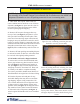
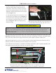
1. Route wiring from end of bundle outlet feed extension through clips alongside arm and chassis, (see
gure10). Round black ground wire routes down arm and to ground post on chassis. Flat black ribbon
wire, (exit sensor cable) routes along arm and across outer chassis to attach to CMC board.
2. Reattach ground wires to side cover. Check all other wiring connections across electronics side of
dispenser to make sure all ttings are secure. Replace side cover plate.
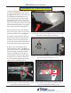
Slide bundle output unit onto end of extension arm
on both sides and fasten with four Torx screws.
3. Once dispenser and all parts are assembled, including side handles, gather original equipment, parts
and shipping material and pack in same box for return to Triton.
NOTE: All wiring is shipped pre-attached to extension unit end and CMC board on the dispenser.
Wiring is not routed along correct path. The following details how ground and control wires
should be placed on the unit. Use caution to keep wiring path away from any moving parts on
electronics side of unit.
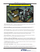
Bill output feed extension arm assembled and in place on dispenser unit. Note
routing of ground wire and black ribbon sensor wire leading to CMC board.
Figure 10
Ground wire connection
Exit sensor cable to CMC board
Notch opening for sensor cable
Wire routing clip
WiriNg AND CoNNECtioNs
Figure 9
5. Once completed, slip extension arms in-
side slots on both sides of upper end at rear
of dispenser. Secure arms to unit by attaching
metal cover bracket using four (4) Torx screws
supplied in shipment and removed in an earlier
step, (see gure 7, 8).
6. Attach bundle output unit extension to ends
of arms using Torx-head screws, (see gure 9).
Use caution when connecting end unit to make
sure wiring ts correctly through slot in end of
arm, (see gure 9, 10). Do not crimp wiring
during assembly.