
Owner Manual

5
NMD 100 ExtENsioN AssEMbly
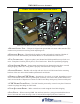
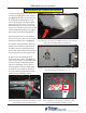
1. Remove the rst top cover. There are
no fasteners holding this cover in place,
(see gure 5). Remove second top cover
by loosening and removing ve T-20
screws along upper side of unit. When
removing, note two of the screws have
different threads. Set screws aside sepa-
rately. Once tops are removed, locate and
remove cardboard packing rod in upper
part of unit. Set aside for reshipment.
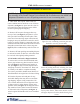
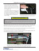
2. Loosen and remove screws holding
side cover in place. With cover removed,
disconnect ground wires, (see gure 6.
3. Separate extension blocks. Dull grey
blocks will assemble for placement on
the side of the unit containing all elec-
tronics. The shiny black blocks will con-
nect and be placed on the opposite side.
4. Remove screws attaching metal
cover brackets to blocks, (see gure 7)
retain screws and set cover bracket aside.
Extension length is determined before
shipment, depending on unit. Blocks
snap together to form extension length,
(ve blocks for 10-inch/two blocks for
ve-inch extension, depending on unit
model). Secure with Torx screws.
Screws attach cover bracket to blocks. Four
screws at right attach assembly to unit.
Remove side cover by loosening screws 1 and 2. Remove
ground wiring from locations 3, 4, 5.
Figure 6
Figure 7
Figure 5
No screws are necessary for removal of top cover. Locate
and remove packing material inside unit.
AssEMbliNg/AttACHiNg ExtENsioN
Once assembled, secure arm assembly to both
sides of dispenser at points shown.
Figure 8