
Owner Manual

3
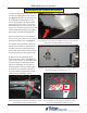
NMD 100 ExtENsioN AssEMbly
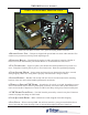
NMD 100 with BOU extension, cover plates and lifting handles attached.
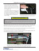
1. buNDlE output uNit -- This part is shipped with ground and exit sensor cables attached. Use
caution not to put tension on wiring while unpacking item.
2.
ExtENsioN bloCks -- These blocks t together to make up length of extension. Number of
blocks sent will be determined by unit model. Blocks are secured with Torx-head screws.
3.
top CovEr plAtEs -- Upper rear plate is not fastened and folds upward from top of unit to re-
move. Front plate is held in place by ve (5) Torx-head screws. Plates are taped during shipping.
4.
NotE stACkEr Motor -- Inspect motor and mount for any damage that may have occurred
during shipping. Make sure wiring cable is properly seated and unit is snug on chassis.
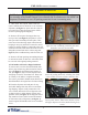
5.
liftiNg HANDlEs -- Handles will not ship with unit. Screws will be located in the mounting
brackets of the new unit to allow handle replacement from old unit.
6.
WiriNg to grouND/CMC boArD -- Ground wire, (ve-inch, or 10-inch, depending on exten-
sion) is routed down arm to attach to ground point on chassis. Exit sensor cable, (black ribbon wire)
routes across outside of dispenser to connect to CMC board. Keep wiring away from moveable parts.
7.
CMC boArD/CovEr plAtE -- The CMC board is protected by a metal cover plate. Extension
control wire plugs into tting on CMC board.
8.
NotE quAlifiEr Doors -- Make certain doors remain snapped closed after shipping.
9.
lift poiNts -- When removing NMD 100 unit from inner box, grasp green-marked bracket on
front of unit and main motor housing at rear of unit and lift straight up and out of inner box.
Figure 1
1
3
5
4
2
6
7
8
9
9
pArts AND AssEMbly iDENtifiCAtioN