
Guide

9
Ft7000 Controller PC Hard drive remove and rePlaCement ProCedures
installation of the ft7000 ContRolleR PC assembly
inStalling the ft7000 controller Pc in the control bay
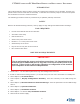
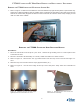
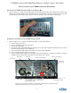
1. Refer to Figure 17. Make sure all cables are clear and that the top right access panel is open all the way.
Grasp the U-shaped handle at the top middle of the Controller PC. Hold the Controller PC level with
the top shelf in the Control Bay. Place it on the front edge and slide it all the way back.
connecting the cableS to the ft7000 controller Pc
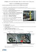
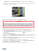
1. Refer to Figure 18. Connect the following cables to the Controller PC:
a. Plug in the AC line cord,
b. Plug in the RSP mouse and keyboard,
c. Plug in the LAN cable,
d. Pluginthe2offwhiteUSBcables(ControllerPCtoUCVmainboardandControllerPCtoControl
PanelDockingBoard)toanyUSBport,
e. PlugintheblackUSBcable(ControllerPCtoUPS)toanyUSBport,
f. Plug in the black audio cable to Line Out.
g. PluginLVDS1(RearDisplay)andLVDS2(ControlPanelDisplay-Itmaybenecessarytoplugin
LDVS2beforepushingtheControllerPCtothebackoftheshelf).
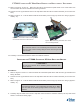
Figure 18. Rear view of Controller PC Assembly identifying the cables that must
be disconnected before removing it from the ATM.
Audio Cable
(LineOut)
AC line cord
RSP Mouse
LAN cable
USB Controller PC to UCV GPIO Board
and Controller PC to Control Panel
DockingBoardcables)
USB Controller PC to
UPS interface cable
LVDS1(RearDisplay)
LVDS2(FrontDisplay)
RSP Mouse
Figure 17. Installing the Controller PC.