
Guide

8
Ft7000 Controller PC Hard drive remove and rePlaCement ProCedures
5. Closeandsecuretheretainerbracketwiththetwo(2)thumbscrews.
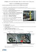
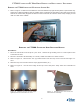
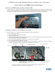
8. Refer to Figure 12. Carefully place the bracket and hard drive into the case, with the threaded
stand-offs on the bottom half of the bracket facing the rear.
6. RefertoFigure13.Alignthethreadedstandoffsonthebracketwiththefour(4)mountingholes
on the rear panel of the case.
7. Secure the hard drive retainer bracket to the case with the
four(4)mountingscrews.
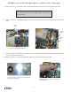
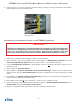
8. Refer to Figure 14. Reconnect the hard drive power and data
cables.
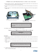
9. Refer to Figure 15. Place the top cover on the case, over-
lapping the front edge approximately 1/4”. Make sure both
L-shapedtabsonbothsidesofthetopcovertintothecorre-
sponding slots on the Controller PC case. Push the top cover
backwarduntilitstops(approximately1/4”).Makesurethe
tabsalongthebackedgeofthetopcovertundertheback
edge of the Controller PC case.
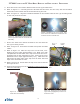
10. Refer to Figure 16. Screw down the top cover at the front left
and right corners.
11. Perform the procedure for the “Installation of the FT7000 Con-
troller PC Assembly”.
Figure 13. View of the Controller PC as-
sembly identifying the four screw loca-
tions where the hard drive and bracket are
mounted to the Controller PC.
Figure 12. Installing the hard drive and
mounting bracket into the Controller PC
assembly.
Figure 14. HDD Data and Power ca-
bles.
D a t a
Cable
P o w e r
Cable
Figure16.Securethetwo(2)mount-
ingscrews(highlighted)ontheCon-
troller PC cover.
Figure 15. Installing the cover on the
Controller PC assembly.