Controller PC Hard Drive Remove and Replace Procedure Guide (Model FT7000) TDN 07103-00195 08/2008 Corporate Headquarters: 522 E. Railroad Street Long Beach, MS 39560 Phone: (228) 868-1317 Fax: (228) 868-0437 COPYRIGHT NOTICE © 2008 Triton. All Rights Reserved. TRITON logo is a registered trademark of Triton Systems of Delaware.
FT7000 Controller PC Hard Drive Remove and Replacement Procedures TABLE OF CONTENTS Introduction. ................................................................................................................... 3 Safety. .................................................................................................................................3 Tools Required...................................................................................................................3 Preliminary Requirements.
FT7000 Controller PC Hard Drive Remove and Replacement Procedures INTRODUCTION This guide details the steps to safely remove and replace the Hard Drive as a separate, internal component of the FT7000 Controller PC Assembly. It includes the necessary steps to remove and replace the Controller PC from the FT7000 terminal. The following procedures must be performed by a qualified (trained) technician. SAFETY Observe all standard safety practices, as they apply to High Voltage and Electrostatic discharge.
FT7000 Controller PC Hard Drive Remove and Replacement Procedures Removal of the FT7000 Controller PC Assembly Shutdown and Disconnecting the Cables from the FT7000 Controller PC 1. Press Cntrl + 1 on the RSP keyboard and log into Management Functions. 2. Install a USB external storage device (i.e. thumb drive) into one of the Controller PC’s USB ports. 4. Select Option 8, Terminal Status. 5. Select Option 1, Display Configuration Summary. Save the summary to the USB storage device. 6.
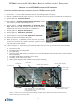
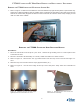
FT7000 Controller PC Hard Drive Remove and Replacement Procedures Removing the FT7000 Controller PC from the Control Bay 1. Refer to Figure 3. Make sure all cables are clear and that the top right access panel is open all the way. Grasp the U-shaped handle at the top middle of the Controller PC and slowly pull it away from the top shelf in the Control Bay Support the bottom of the Controller PC with the other hand, keeping it level until it is clear of the cabinet. Figure 3. Removing the Controller PC.
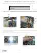
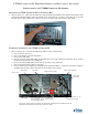
FT7000 Controller PC Hard Drive Remove and Replacement Procedures 7. Refer to Figure 6. The hard drive is located at the back left corner of the Controller PC case. **CAUTION** Use extreme caution when handling static sensitive electronic devices. 8. Refer to Figure 7. Carefully unplug the power and data cables along the right side of the hard drive. Hard Drive Power Cable D a t a Cable Figure 7. HDD Data and Power cables. Figure 6. Hard Drive location. 9. Refer to Figure 8.
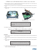
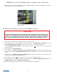
FT7000 Controller PC Hard Drive Remove and Replacement Procedures 11. Refer to Figures 10 and 11. Place the hard drive and bracket upside down on a clean static free work surface with the 2 thumbscrews facing forward. 12. Loosen the two (2) thumbscrews on the top half of the hard drive retainer bracket (now on the bottom). 13. Refer to Figure 11. Pull the bottom half of the bracket (now on top) up as far as it will go (approximately. 2”). Figure 10.
FT7000 Controller PC Hard Drive Remove and Replacement Procedures 5. Close and secure the retainer bracket with the two (2) thumbscrews. 8. Refer to Figure 12. Carefully place the bracket and hard drive into the case, with the threaded stand-offs on the bottom half of the bracket facing the rear. 6. Refer to Figure 13. Align the threaded standoffs on the bracket with the four (4) mounting holes on the rear panel of the case. Figure 13.
FT7000 Controller PC Hard Drive Remove and Replacement Procedures Installation of the FT7000 Controller PC Assembly Installing the FT7000 Controller PC in the Control Bay 1. Refer to Figure 17. Make sure all cables are clear and that the top right access panel is open all the way. Grasp the U-shaped handle at the top middle of the Controller PC. Hold the Controller PC level with the top shelf in the Control Bay. Place it on the front edge and slide it all the way back. Figure 17.
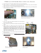
FT7000 Controller PC Hard Drive Remove and Replacement Procedures 2. Refer to Figure 19. If used, install the retainer bracket (yellow) on the top right side of the cabinet. Hand-tighten the two (2) thumbscrews. Figure 19. The location of the yellow retaining bracket. System Start up and Operational Testing of the FT7000 PC Controller **IMPORTANT** Restoring the parameters that were saved at the beginning of this procedure will save time re-configuring the terminal.