
Owner Manual

1A-21
RL5000
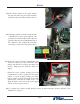
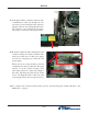
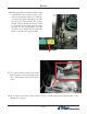
18. Route the security module communication and
security module power cable around the unit’s
main power cable and over the power supply
(red arrows). Plug the power cable into the
power supply.
Ensure all excess security module power and
communication cable is pulled into the upper
cabinet. Loop the security module power
cable back on itself to condense the length of
the cable. TY Wrap the cable and cut off the
excess. TY Wrap the cables on the side of the
power supply and cut off excess (green arrows).
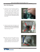
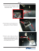
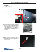
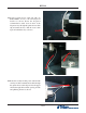
17. In the upper cabinet, route the security module
communication cable up through all four
previously loosened wire plate cable clips and
plug the cable into the docking/mainboard in
the “dispenser” jack. Tighten the wire plate
cable clips to secure the control panel cables.
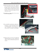
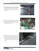
19. To complete the security module install, perform “Synchronizing the Security Module to the
Mainboard” on page 3.