
Owner Manual

1A-18
EJ TO SECURITY MODULE UPGRADE PROCEDURES
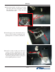
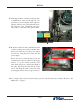
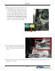
10. Route the all the cables through the left lower
cable clip (red arrow). Continue to route the
security module power cable and the security
module communication cable up through the
upper left cable clip as shown (blue arrow).
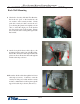
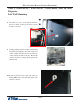
9. Attach four quick release cable clips to the
mounting bracket using four 8/32 Hex Nuts.
Ensure the orientation of the clips matches the
picture as shown. Route the cables through the
middle cable clip as shown.
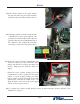
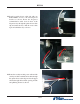
8. Obtain the Security Module Flat Bracket.
Insert the two posts on the bracket into the
two notches on the security module. Gently
push the security module towards the two
posts, fl exing the plastic ends slightly on both
sides, to insert the single post on the bracket
into the single notch on the module. Ensure
the security module is sitting fl ush against the
fl at bracket.
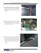
Vault # 03015-00064 / 03015-00200 / 03015-00227 with an SDD Dispenser
Back Wall Mounting